Ammonia spraying device and flue gas denitration device

A flue gas and denitrification technology, which is applied in the field of ammonia injection devices and flue gas denitrification devices, can solve the problems of large resistance of denitrification and ammonia injection devices, achieve the effect of increasing the path and area, reducing the blocking area, and improving the efficiency of ammonia removal

Pending Publication Date: 2021-06-18
CHINA HUADIAN ENG +1
View PDF0 Cites 3 Cited by
  • Summary
  • Abstract
  • Description
  • Claims
  • Application Information

AI Technical Summary

Problems solved by technology

[0004] Therefore, the technical problem to be solved by the present invention is to overcome the defect that the denitrification ammonia injection device in the prior art has relatively large resistance, thereby providing an ammonia injection device and a flue gas denitrification device that can reduce resistance

Method used


Image

  • Ammonia spraying device and flue gas denitration device
  • Ammonia spraying device and flue gas denitration device

Examples


Embodiment 1

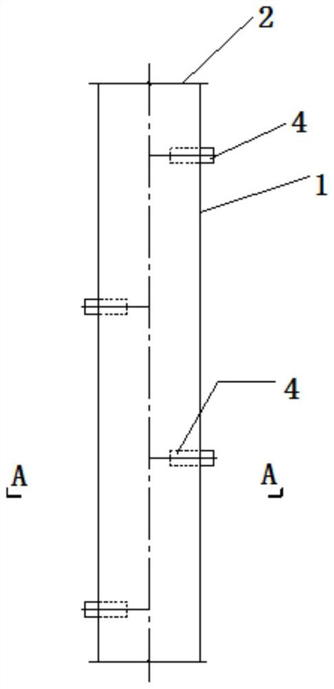
[0029] At present, the power plant is undergoing a new round of ultra-low emission transformation projects, which involves the transformation and replacement of a large number of flue gas denitrification devices. The modified or newly built denitrification reactor will install many ammonia injection devices in the vertical section of the reactor for the injection of ammonia gas. The ammonia gas reacts with the nitrogen oxides in the flue gas in the reactor, and the nitrogen oxides remove. The existing ammonia injection device is made of circular steel pipes, holes are opened on the circular pipes, and nozzles of different angles are cross-welded to realize the injection coverage of ammonia gas. Ammonia injection pipes are arranged side by side and parallel inside the flue. The projected area of ​​the pipes occupies almost half of the cross-sectional area of ​​the entire flue. The effective cross-section that the flue gas can pass through is reduced, which greatly increases the...

Embodiment 2

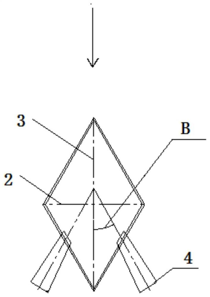
[0043] This embodiment provides a flue gas denitrification device, comprising the ammonia injection device and the flue provided in the above embodiments, and the ammonia injection pipe 1 of the ammonia injection device is horizontally arranged in the flue. Because the short diagonal 2 of the cross-section of the ammonia injection pipeline 1 is perpendicular to the flow direction of the flue gas in the flue, and the long diagonal 3 is parallel to the flow direction of the flue gas in the flue, the rhombus cross-sectional area of ​​the ammonia injection pipeline 1 and In the prior art, under the premise that the circular cross-sectional area is equal, that is, under the condition that the ammonia injection flow rate is constant, since the short diagonal line 2 is perpendicular to the flue gas flow direction, under the premise that the length of the ammonia injection pipeline 1 is constant , the projected area of ​​the ammonia injection pipeline 1 can be greatly reduced, and the ...


PUM


Abstract

The invention relates to the technical field of environmental protection, in particular to an ammonia spraying device and a flue gas denitration device. The ammonia spraying device comprises an ammonia spraying pipeline suitable for being horizontally arranged in a flue, and a nozzle, wherein the cross section of the ammonia spraying pipeline is in a rhombus shape, the short diagonal line of the rhombus is perpendicular to the flowing direction of flue gas in the flue, the long diagonal line of the rhombus is parallel to the flowing direction of flue gas in the flue; and the nozzle is arranged on the ammonia spraying pipeline. As the short diagonal is perpendicular to the flowing direction of the flue gas, the projection area of the ammonia spraying pipeline is the product of the length of the short diagonal and the length of the ammonia spraying pipeline on the premise that the length of the ammonia spraying pipeline is not changed, the blocking area to the flue gas can be greatly reduced, the deamination efficiency of the system is ensured, the resistance of the system is effectively reduced, the mass transfer path and area are increased, and the deamination efficiency is improved. In addition, due to the rhombus shape, the flow of the flue gas can be guided, the flue gas flows smoothly, and the abrasion to the ammonia spraying pipeline is small.

Description

technical field [0001] The invention relates to the technical field of environmental protection, in particular to an ammonia injection device and a flue gas denitrification device. Background technique [0002] At present, the power plant is undergoing a new round of ultra-low emission transformation projects, which involves the transformation and replacement of a large number of flue gas denitrification devices. The modified or newly built denitrification reactor will install many ammonia injection devices in the vertical section of the reactor for the injection of ammonia gas. The ammonia gas reacts with the nitrogen oxides in the flue gas in the reactor, and the nitrogen oxides remove. The existing ammonia injection device is made of circular steel pipes, holes are opened on the circular pipes, and nozzles of different angles are cross-welded to realize the injection coverage of ammonia gas. [0003] Ammonia injection pipes are arranged side by side and parallel inside ...

Claims


Application Information

Patent Timeline
Patent Type & Authority Applications(China)
IPC IPC(8): B01D53/79B01D53/56
CPCB01D53/56B01D53/79B01D2251/2062B01D2258/0283
Inventor 夏怀鹏白永锋吴冲王凯亮汪洋李伟
Owner CHINA HUADIAN ENG
Why Eureka
Try Eureka