


Quick Research
Generate reliable direction feasibility study reports for your R&D in just a few steps.

Technical Q&A
Discover and master advanced knowledge NOW. Basics, ideas, possibilities, all at once.

Find Solutions
As an expert in R&D theories, this can generate solutions to your technical problems instantly.

Evaluate Feasibility
Analyze your overall solution with one click, know your potential R&D risks in advance.

Monitor Landscape
Get weekly tech updates, stay abreast of the latest tech innovations and key insights.
Auxiliary heating type non-woven fabric production shaping device
A setting device, non-woven technology, which is applied to the device for coating liquid on the surface, the cutting of textiles and papermaking, textile materials, etc. , Improve drying efficiency and facilitate disassembly and installation
- Summary
- Abstract
- Description
- Claims
- Application Information
AI Technical Summary
Problems solved by technology
Method used
Image

Examples
Embodiment 1
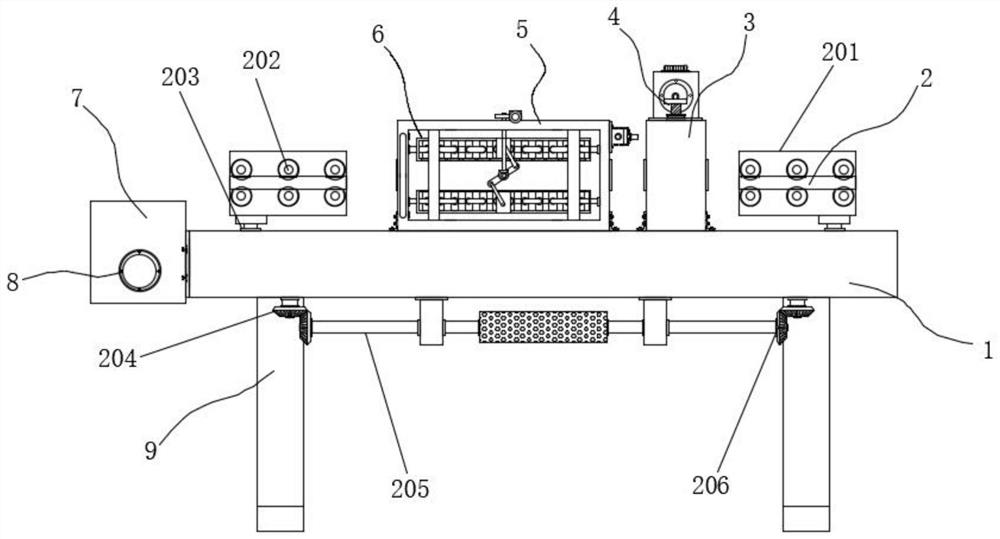
[0038] Example 1: See Figure 1-7 , a heat-assisted non-woven production shaping device, including a base 1, a shell 3, an oven 5 and a fixing seat 7, the two sides of the top of the base 1 are respectively provided with a positioning structure 2, the middle position of the top of the base 1 One side of the base 1 is fixedly connected with a housing 3, and the inside of the housing 3 is provided with a liquid coating mechanism 4, and the middle position of the top of the base 1 is fixedly connected with an oven 5, and the inside of the oven 5 is provided with a drying mechanism 6, basically The two ends on one side of the seat 1 are respectively fixedly connected with a fixed seat 7, and the top between one end of the fixed seat 7 is provided with a cutting structure 10, and the four corners at the bottom of the base 1 are respectively fixedly connected with a pillar 9, and the fixed seat 7 The bottom between one end is provided with a winding mechanism;
[0039] The drying m...
Embodiment 2
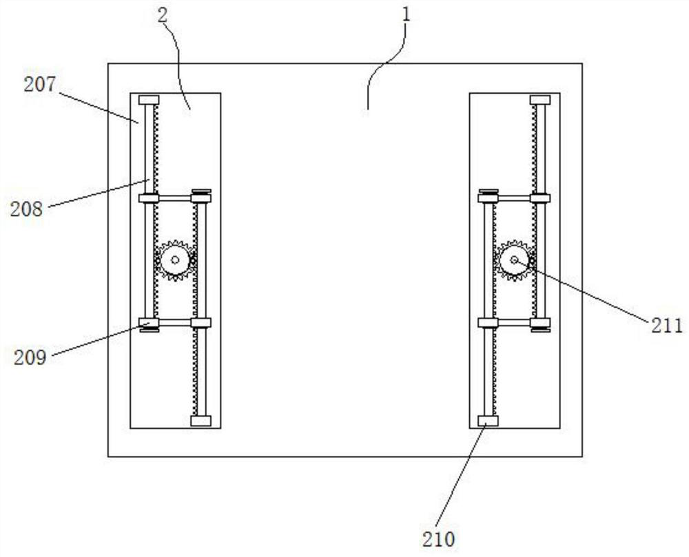
[0043] Embodiment 2: The positioning structure 2 is composed of a guide block 201, a roller 202, a chute 203, a first gear 204, a rotating rod 205, a second gear 206, a cavity 207, a rack bar 208, a limit block 209, and a connecting block 210 Composed of a central gear 211, the rotating rod 205 is movably connected between the two sides of the bottom of the base 1, the two sides of the rotating rod 205 are respectively fixedly connected with the second gear 206, and the cavities 207 are respectively arranged on both sides inside the base 1 , the top of the cavity 207 is provided with a chute 203, the middle position inside the cavity 207 is movably connected with a central gear 211, and the bottom end of the central gear 211 is fixedly connected with the first gear 204 through a transmission rod, and the two sides of the central gear 211 Rack bars 208 are respectively arranged on the sides, and the two ends between one side of the rack bars 208 are respectively movably connecte...
Embodiment 3
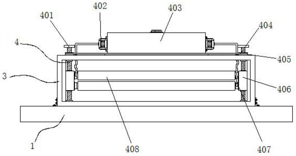
[0047] Embodiment 3: The liquid application mechanism 4 is made up of screw rod 401, water pump 402, liquid storage tank 403, chain 404, transmission gear 405, threaded block 406, hose 407 and brush tube 408, and the top of liquid storage tank 403 is fixedly connected on the shell The top of the body 3 and both sides of the liquid storage tank 403 are respectively fixedly connected with a water pump 402. The model of the water pump 402 can be XC-SB-01. A transmission gear 405 is movably connected with the housing 3, and a chain 404 is movably connected between one side of the transmission gear 405, a threaded block 406 is movably connected to the outside of the screw 401, and a threaded block 406 is movably connected between one end of the threaded block 406. Two sets of brush tubes 408, a hose 407 is fixedly connected between the brush tube 408 and one side of the water pump 402;
[0048] The screw rod 401 is embedded in the inside of the threaded block 406, and the screw rod...
PUM
 Abstract
Description
Claims
Application Information
 - R&D Engineer
- R&D Manager
- IP Professional
- Industry Leading Data Capabilities
- Powerful AI technology
- Patent DNA Extraction
Browse by: Latest US Patents, China's latest patents, Technical Efficacy Thesaurus, Application Domain, Technology Topic, Popular Technical Reports.
© 2024 PatSnap. All rights reserved.Legal|Privacy policy|Modern Slavery Act Transparency Statement|Sitemap|About US| Contact US: help@patsnap.com