Automatic multifunctional machine part machining device

A technology for multi-functional machinery and processing devices, applied in the field of mechanical processing, can solve the problems of reducing the diversity of devices, affecting the practicability of the devices, affecting the working efficiency of the devices, and achieving the effects of improving the degree of automation, improving work efficiency, and improving practicability

Pending Publication Date: 2021-06-18
陈增法
View PDF5 Cites 0 Cited by
  • Summary
  • Abstract
  • Description
  • Claims
  • Application Information

AI Technical Summary

Problems solved by technology

[0003] Among the existing mechanical processing devices, the automation degree of the punching device is low, which affects the working efficiency of the d

Method used


Image

  • Automatic multifunctional machine part machining device
  • Automatic multifunctional machine part machining device
  • Automatic multifunctional machine part machining device

Examples


Embodiment 1

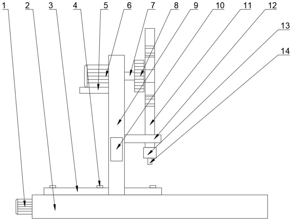
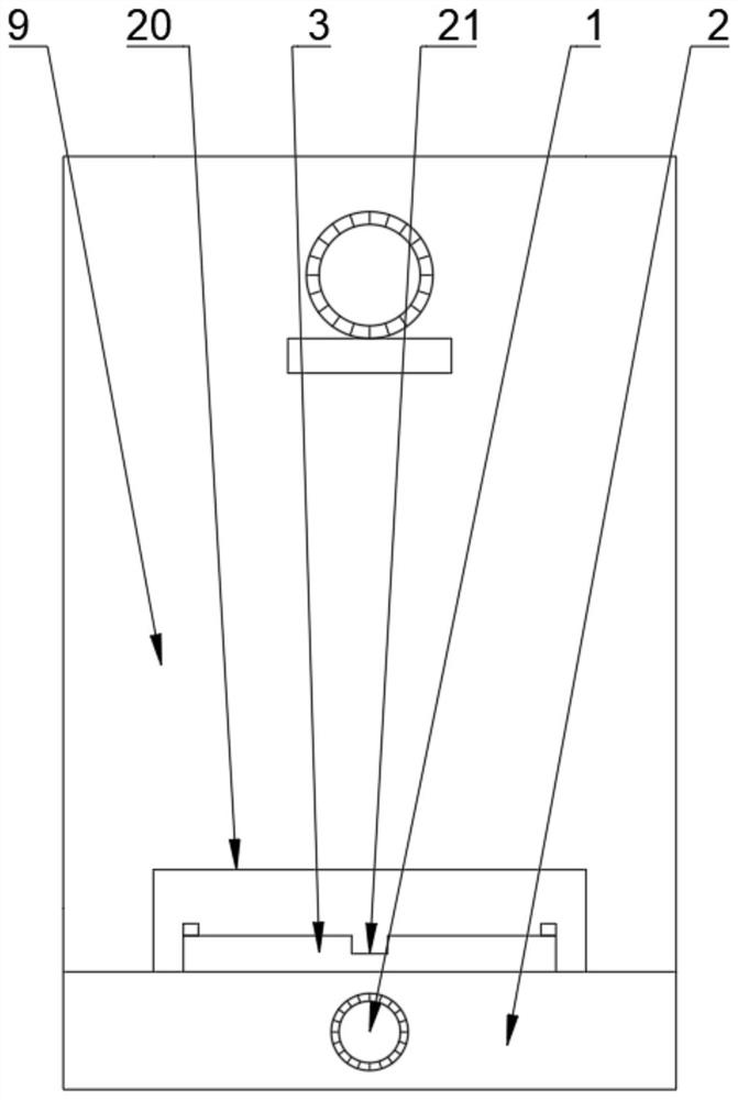
[0025] see Figure 1~5 , in Embodiment 1 of the present invention, an automatic multifunctional mechanical parts processing device includes a base 2, a fixed assembly 4, a moving mechanism, a bracket 9, a lifting mechanism, a controller 10, a punching head mounting assembly 13, and a punching head 14;

[0026] The lifting mechanism includes a lifting motor fixing plate 5, a lifting motor 6, a front driven shaft 7, a front driven gear 8, a lifting rod 11, a limit rod 12, a driving shaft 15, a driving gear 16, a front ring gear 23, a gear Bar 24, the rear driven gear 25, the rear driven shaft 26 and the rear ring gear 27, the lifting motor fixing plate 5 is fixedly connected above the left side of the support 9, and the lifting motor 6 is fixedly connected to the top of the lifting motor fixing plate 5. On the upper surface, the drive shaft 15 is horizontally placed and rotatably connected to the middle part of the bracket 9, the left end of the drive shaft 15 is connected to th...

Embodiment 2

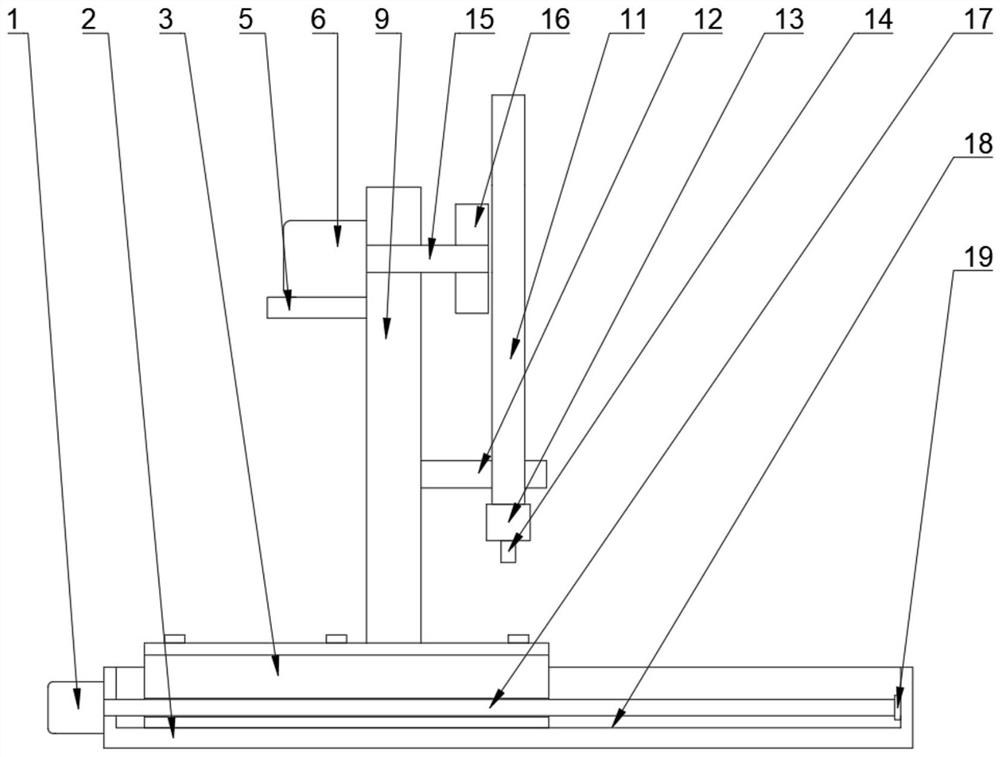
[0028] see Figure 1~5 The main difference between this embodiment 2 and embodiment 1 is that the moving mechanism includes a moving motor 1, a workbench 3, a screw 17 and a rotating seat 19, and the screw 17 is installed horizontally inside the base 2, and is connected with the base The seat 2 is connected in rotation, the rotating seat 19 is fixedly connected to the inner side of the right side of the base 2, the right end of the chute 18 is installed in the rotating seat 19, and is connected in rotation with the rotating seat 19, and the mobile motor 1 is fixedly connected to the bottom of the base 2. On the left side, the driving shaft of the mobile motor 1 is connected to the screw rod 17 through a coupling, and the workbench 3 is installed inside the base 2, and is threaded with the screw rod 17, and is slidingly connected with the base 2; when it needs to move , start the mobile motor 1, and under the action of the mobile motor 1, the screw rod 17 is driven to rotate. S...


PUM


Abstract

The invention discloses an automatic multifunctional machine part machining device, and relates to the technical field of machining. The automatic multifunctional machine part machining device comprises a base, a fixing assembly, a moving mechanism, a support, a lifting mechanism, a controller, a stamping head mounting assembly and a stamping head; the moving mechanism is slidably connected into the base; the fixing assembly is fixedly connected to the upper surface of a workbench; the support is fixedly connected to the middle of the upper surface of the workbench; the controller is fixedly connected to the front side face of the support; the lifting mechanism is fixedly connected to the side face of the support; the stamping head mounting assembly is fixedly connected to the lower bottom face of a lifting rod; and the stamping head is detachably connected to the lower end of the stamping head mounting assembly. The automatic multifunctional machine part machining device has the beneficial effects that the automation degree of punching is improved through the lifting mechanism, the working efficiency of the device is improved, and time is saved; and the controller can control the moving distance of the workbench, equal-distance punching can be achieved, equal-distance punching of different distances can also be achieved, and the practicability of the device is further improved.

Description

technical field [0001] The invention relates to the technical field of mechanical processing, in particular to an automatic multifunctional mechanical accessory processing device. Background technique [0002] A machine tool refers to a machine that manufactures a machine, also known as a machine tool or a tool machine, and is customarily referred to as a machine tool. Generally divided into metal cutting machine tools, forging machine tools and woodworking machine tools, etc., there are many ways to process mechanical parts in modern machinery manufacturing: in addition to cutting, there are casting, forging, welding, stamping and extrusion, etc., but all of which require high precision and Parts with finer surface roughness requirements generally need to be final processed on machine tools by cutting methods. Currently, the machine tools used in production mainly include lathes, milling machines, drilling machines, grinding machines, planers, etc. Large factories or profes...

Claims


Application Information

Patent Timeline
IPC IPC(8): B21D28/24B21D37/00
CPCB21D28/002B21D28/24B21D37/00
Inventor 王逸群卞善中
Owner 陈增法
Why Eureka
Try Eureka