
Reinforced end mill for machining side wall

A technology for end mills and strengthening components, applied in milling cutters, metal processing equipment, manufacturing tools, etc., can solve the problems of easy breakage at the connection between the milling cutter and the shank, low service life, and easy damage to the milling cutter. The phenomenon of knife dropping, improving the service life and prolonging the service life

Active Publication Date: 2021-06-18
深圳市瑞利泰德精密涂层有限公司
View PDF8 Cites 0 Cited by
  • Summary
  • Abstract
  • Description
  • Claims
  • Application Information

AI Technical Summary

Problems solved by technology

[0003] The end mills in the prior art have the following disadvantages: First, when the diameter of the milling cutter is large, even if the tool handle and the tool holder are cleaned very clean, there may still be a tool drop accident, resulting in the scrapping of the workpiece Second, when the milling cutter is being processed, the connection between the milling cutter and the handle is easy to break, resulting in easy damage to the milling cutter and low service life

Method used


Image

  • Reinforced end mill for machining side wall
  • Reinforced end mill for machining side wall
  • Reinforced end mill for machining side wall

Examples


Embodiment 1

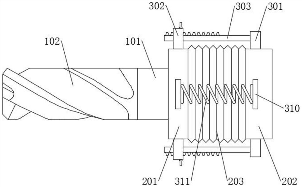
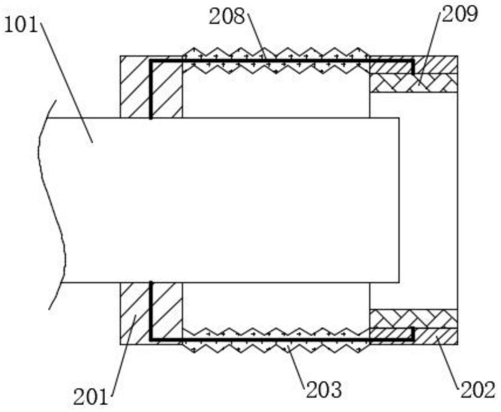
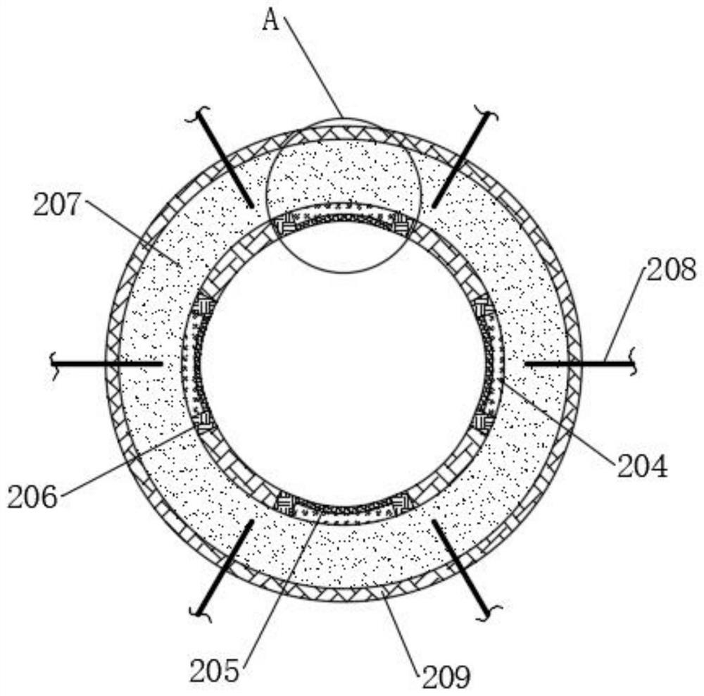
[0033] see Figure 1-5 , a reinforced end mill for processing side walls, including a cutter body, the cutter body includes a shank 101, a blade 102, the blade 102 is fixedly connected to one end of the shank 101, and a self-reinforcing component is arranged on the outer wall of the shank 101 , the self-reinforcing assembly includes a fixed collar 201 and a movable support ring 202. The fixed collar 201 is fixedly sleeved on the outer wall of the blade 102, and the movable support ring 202 is movably sleeved on the end of the handle 101 away from the blade 102. The fixed sleeve The connecting film cover 203 is connected between the ring 201 and the movable support ring 202, and the connecting film cover 203 is arranged in a folded shape, and the connecting film cover 203 is made of a flexible material, so that the connecting film cover 203 can be contracted and folded, and then the movable support The ring 202 can move towards the direction close to the fixed collar 201, the i...


PUM


Abstract

The invention discloses a reinforced end mill for machining a side wall, and belongs to the technical field of end mills. A special self-reinforcing assembly can be arranged, during machining, heat generated by friction between a cutter body and a workpiece can be used as a triggering condition, so that a double-phase trigger body absorbs heat and is converted into a liquid state, the cutter body can be cooled, and therefore the loss of the cutter body is reduced; after the double-phase trigger body is converted into the liquid state, the size can be increased, so that an attaching inner plate is extruded to be attached to a cutter handle, and then the connection between the cutter body and the cutter handle is enhanced; on one hand, the occurrence of the cutter falling phenomenon can be effectively reduced, on the other hand, the occurrence of the cutter body breaking phenomenon can be reduced, so that the service life of the cutter body is effectively prolonged; and through the arrangement of an adjustable convenient-to-install assembly, a movable supporting ring can be moved and adjusted in the direction close to a fixed lantern ring, so that the installation of the cutter body is not hindered, the cutter body can be conveniently installed on the cutter handle, and the practicability is greatly improved.

Description

technical field [0001] The invention relates to the technical field of end mills, in particular to a reinforced end mill for processing side walls. Background technique [0002] A milling cutter is a rotating tool with one or more teeth for milling. When working, each knife tooth cuts off the allowance of the workpiece intermittently in turn. Milling cutters are mainly used for machining planes, steps, grooves, forming surfaces and cutting off workpieces on milling machines. The end mill is a kind of milling cutter. The main cutting edge of the end mill is on the cylindrical surface, and the cutting edge on the end face is the secondary cutting edge. When working, the feed motion cannot be made along the axial direction of the milling cutter. End mills can be used in machining fields such as side machining, groove machining, and curved surface machining. There are also a wide variety of end mills that can be used for various machining forms. [0003] The end mills in th...

Claims


Application Information

Patent Timeline
Patent Type & Authority Applications(China)
IPC IPC(8): B23C5/00B23C5/02B23C5/28
CPCB23C5/00B23C5/02B23C5/28
Inventor 李珊珊
Owner 深圳市瑞利泰德精密涂层有限公司
Learn More