Heavy oil hydrogenation method and system

A heavy oil hydrogenation and heavy oil technology, which is applied in the fields of hydrogenation treatment process, petroleum industry, and hydrocarbon oil treatment, can solve problems such as poor system stability, increased equipment investment, and potential safety hazards, so as to reduce potential safety hazards, save energy consumption, The effect of increasing operating efficiency

Pending Publication Date: 2021-06-18
SINOPEC ENG +1
View PDF6 Cites 0 Cited by
  • Summary
  • Abstract
  • Description
  • Claims
  • Application Information

AI Technical Summary

Problems solved by technology

In actual production, the high temperature and high pressure in the system will lead to serious safety hazards if the reactor is switched online, the catalyst is replaced, and the operations such as vulcanization and temperature rise are carried out without stopping the device. Therefore, it is still unavoidable to stop the operation.
[0007] The existing technology has been improved in terms of technology and equipment. Although the operating cycle of the device can be extended to a certain extent, there are problems such as complex operation, poor system stability, increased equipment investment, and potential safety hazards.

Method used


Image

  • Heavy oil hydrogenation method and system
  • Heavy oil hydrogenation method and system

Examples


Embodiment 1

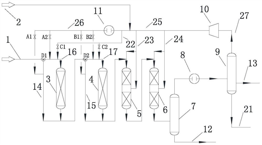
[0073] The heavy oil hydrogenation system of this embodiment is as figure 1 As shown, the system includes a heavy oil inlet 1, a first hydrogenation protection reactor 3, a second hydrogenation protection reactor 4, a first hydrogenation reactor 5, a second hydrogenation reactor 6, a hot high-pressure separator 7, Hot high fraction gas heat exchanger 8 , cold high fraction separator 9 and circulating hydrogen compressor 10 .

[0074] A first inlet pipeline 16 is connected between the heavy oil inlet 1 and the inlet of the first hydrogenation protection reactor 3, and the reaction oil gas outlet of the first hydrogenation protection reactor 3 is connected with the inlet of the second hydrogenation protection reactor 4. There is a second inlet pipeline 17; the outlet of the second hydrogenation protection reactor 4 communicates with the inlet of the first hydrogenation reactor 5 through the second outlet pipeline. A first jumper 14 is also provided between the heavy oil inlet 1...

Embodiment 2

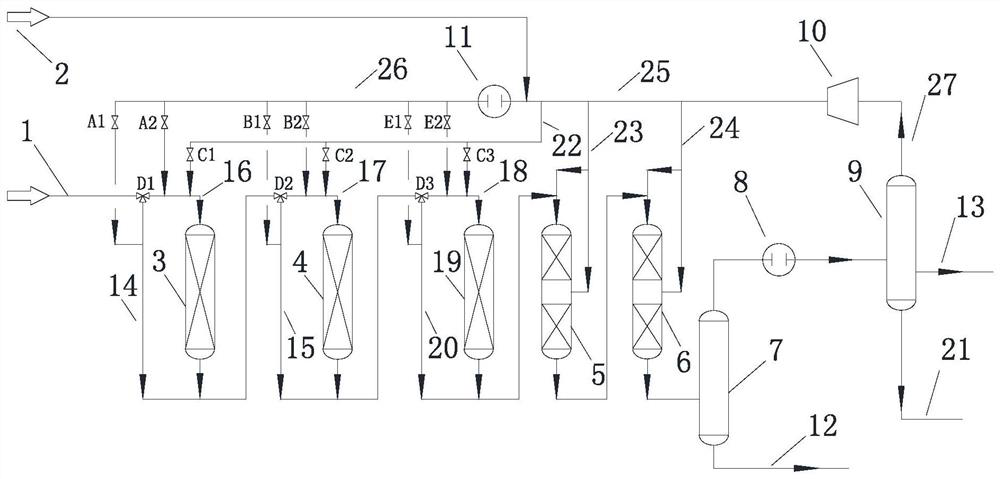
[0089] The heavy oil hydrogenation system of this embodiment is as figure 2As shown, the system includes a heavy oil inlet 1, a first hydrogenation protection reactor 3, a second hydrogenation protection reactor 4, a third hydrogenation protection reactor 19, a first hydrogenation reactor 5, a second hydrogenation reaction device 6, hot high pressure separator 7, hot high fraction gas heat exchanger 8, cold high fraction separator 9 and circulating hydrogen compressor 10.

[0090] Such as figure 2 As shown, the heavy oil hydrogenation system of the heavy oil hydrogenation system of this embodiment is basically the same as that of Embodiment 1, the difference is that the system of this embodiment adds a third hydrogenation protection reactor 19, and the third hydrogenation protection reaction The inlet of device 19 communicates with the outlet of the second hydrogenation protection reactor 4 through the third inlet pipeline 18, and a third span is arranged between the outlet...


PUM

PropertyMeasurementUnit
densityaaaaaaaaaa
densityaaaaaaaaaa

Abstract

The invention relates to a heavy oil hydrogenation method and a system. The system comprises a heavy oil inlet (1), a first hydrogenation protection reactor (3), a second hydrogenation protection reactor (4), hydrogenation reaction equipment, gas-liquid separation equipment and a recycle hydrogen compressor (10). According to the invention, the replacement period of the catalyst of the reactor is protected to be matched with the repair period of a refinery plant by switching the reaction equipment on line, and the operation period of the heavy oil hydrogenation device can be prolonged by 50-300%, so that the operation efficiency of the heavy oil hydrogenation device is increased, the economical efficiency is improved, the system stability is good, and the potential safety hazard is obviously reduced.

Description

technical field [0001] The present disclosure relates to a heavy oil hydrogenation method and a system thereof. Background technique [0002] With the heavy and inferior crude oil, increasingly stringent environmental protection requirements, increasing market demand for light oil products, and increasing requirements for clean petroleum products, more and more refineries use heavy oil in the selection of crude oil processing routes. The heavy oil processing scheme combined with hydrogenation and catalytic cracking, and the heavy oil hydrogenation unit has become the core device in these refineries. [0003] In the heavy oil hydrogenation technology, the fixed bed process is simple, mature and easy to operate, and is the most widely used process. In the fixed bed heavy oil hydrogenation process, the polluting metals in the heavy oil are most easily removed. These heavy metals deposit on the catalyst, which will cause the hydrogenation catalyst to deactivate rapidly, causing...

Claims


Application Information

Patent Timeline
Patent Type & Authority Applications(China)
IPC IPC(8): C10G65/02
CPCC10G65/02
Inventor 乔爱军张旭
Owner SINOPEC ENG
Why Eureka
Try Eureka