Magnetic drive pump with high stability

A magnetic pump and stability technology, which is applied to parts, pumps, pump devices, etc. of pumping devices for elastic fluids, can solve problems such as poor stability performance and component damage, and achieve reduced jitter amplitude and smooth performance High, limited effect Ideal effect

Active Publication Date: 2021-06-18
ANHUI NANFANG CHEM PUMP IND
View PDF6 Cites 0 Cited by
  • Summary
  • Abstract
  • Description
  • Claims
  • Application Information

AI Technical Summary

Problems solved by technology

[0003] Aiming at the deficiencies of the prior art, the present invention provides a magnetic pump with high stability, which has the advantages of ideal stability of the pump body during use, and solves the problem of traditional magnetic pumps. When the pump is in use, the stability performance is not good, and it is easy to cause damage to the components in the pump body

Method used


Image

  • Magnetic drive pump with high stability
  • Magnetic drive pump with high stability
  • Magnetic drive pump with high stability

Examples


Embodiment 1

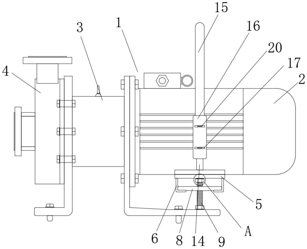
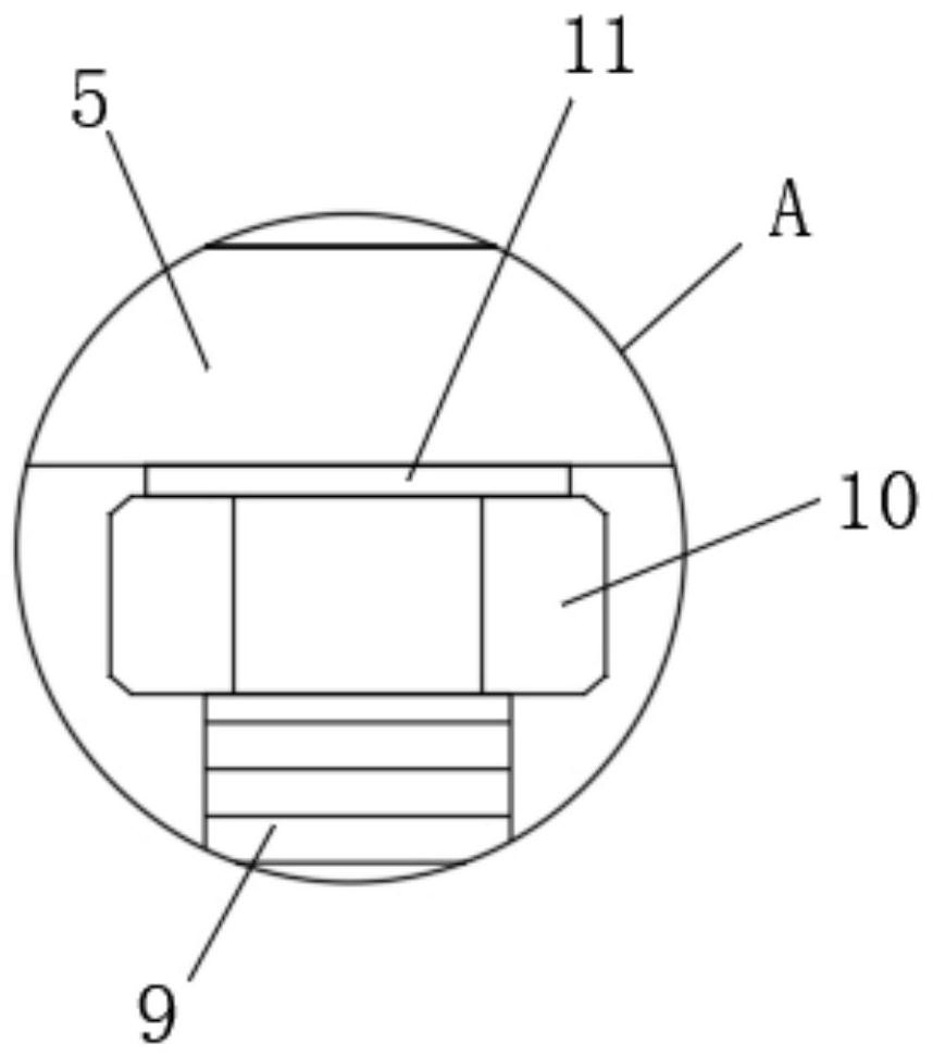
[0036] see Figure 1-3, the magnetic pump with high stability of the present invention includes a magnetic pump main body 1, the magnetic pump main body 1 includes a motor 2, a bracket 3 and a pump casing 4; the bracket 3 includes a support plate, and the inner bottom of the support plate is provided with a slot 12. The bottom of the motor 2 is fixedly welded with the first fixed plate 5, and the left and right sides of the bottom of the first fixed plate 5 are integrally formed with an "L"-shaped receiving plate 6, and the inner bottom of the receiving plate 6 is provided with a concave groove 7 and A connecting plate 8 matching the horizontal and vertical diameters is movably clamped between the insides of the two recessed grooves 7, and the center of the top and bottom of the connecting plate 8 is fixedly connected with a threaded rod 9, and the surfaces of the two threaded rods 9 are threaded. Connected with nuts 10, the sides of the two nuts 10 that are far away from each...

Embodiment 2

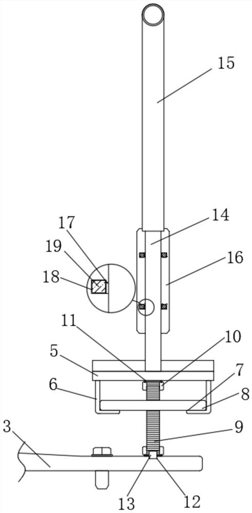
[0038] see Figure 4-5 , the front and the back of the first fixing plate 5 respectively protrude to the front and the back of the bottom of the motor 2, the top of the first fixing plate 5 and the positions close to the front and the back of the motor 2 respectively are fixedly connected with protruding rods 14 along the vertical direction, The outer side of the protruding rod 14 is provided with a grab bar 15 which is convenient for grabbing and transporting the magnetic pump. Before the magnetic pump is installed and during the handling operation, the staff can use one hand to grab the grab bar 15 to lift and apply pressure upwards. , and use the other hand to drag a certain point at the bottom of the pump casing 4, and then lift, carry, and move the magnetic pump.

Embodiment 3

[0040] see Figure 6-7 , the front and bottom of the back of the grab bar 15 are fixedly connected with a second fixed plate 16, and the fronts of the two second fixed plates 16 are provided with openings and plugged with a plug-in board 17, and the plug-in board 17 is close to the two second fixed boards. Two third fixing plates 18 are integrally formed on the opposite side of the two fixing plates 16, and the vertical diameter between the top surface and the bottom of a plurality of third fixing plates 18 is the same as the vertical diameter between the two nuts 10 opposite surfaces. The diameters are equal, and a cavity with a diameter larger than the nut 10 is left between the two third fixing plates 18 close to the plurality of plug-in boards 17 respectively. The side of the third fixing plate 18 away from the plug-in board 17 is fixedly connected with a magnet block 19. The third fixed plate 18 includes a horizontal plate and a vertical plate. The bottom ends of the vert...


PUM


Abstract

The invention relates to the technical field of magnetic drive pumps, and particularly discloses a magnetic drive pump with high stability. The magnetic drive pump comprises a magnetic drive pump body, wherein the magnetic drive pump body comprises a motor, a support and a pump shell, the support comprises a supporting plate, an inserting groove is formed in the bottom of the inner side of the supporting plate, a first fixing plate is fixedly welded to the bottom of the motor, L-shaped bearing plates are integrally formed on the left side and the right side of the bottom of the first fixing plate correspondingly, a connecting plate is clamped into a concave groove, an inserting rod is inserted into an inserting groove, a nut is screwed, one sides, far away from each other, of two metal rings are tightly attached to the first fixing plate and the support, so that the limiting effect on the motor is effectively achieved, the shaking amplitude of the motor in the using process is effectively reduced, the stability of the magnetic drive pump is higher, the situation that the shaking amplitude of the motor is strong in the running process is prevented, and elements in the pump is easy to fall off and damage.

Description

technical field [0001] The invention relates to the technical field of magnetic pumps, in particular to a magnetic pump with high stability. Background technique [0002] The magnetic pump is a branch of the water pump field. It is a new product that applies the working principle of the permanent magnet coupling to the centrifugal pump. It has reasonable design, advanced technology, and has the characteristics of full sealing, no leakage, and corrosion resistance. The magnetic pump is composed of The pump, the magnetic drive, and the motor are composed of three parts. The key component, the magnetic drive, is composed of an outer magnetic rotor, an inner magnetic rotor and a non-magnetic isolation sleeve. However, due to the existence of the motor, during the use of the magnetic pump, The main body of the magnetic pump will shake, causing the balance of the magnetic pump to be damaged, which may cause the accidental drop or even damage of the components in the pump. It often...

Claims


Application Information

Patent Timeline
Patent Type & Authority Applications(China)
IPC IPC(8): F04D13/02F04D13/06F04D29/00F04D29/62
CPCF04D13/024F04D13/06F04D29/007F04D29/628
Inventor 秦晓华潘耀东柳春发侯建明姚兴胜唐昊潘凤建
Owner ANHUI NANFANG CHEM PUMP IND
Why Eureka
Try Eureka