Automatic fluorescence scanning detection equipment and method thereof

A scanning detection, automatic fluorescence technology, applied in the field of fluorescence scanning detection, can solve the problems of user error, complicated operation method setting, inconvenient use, etc.

Pending Publication Date: 2021-06-18
苏州图墨医疗科技有限公司
View PDF10 Cites 1 Cited by
  • Summary
  • Abstract
  • Description
  • Claims
  • Application Information

AI Technical Summary

Problems solved by technology

[0005] The purpose of the present invention is to provide an automatic fluorescence scanning detection device and its method to solve the problem that the operation method of the fluorescence detection device proposed in the above background technology is complicated to set up, which is not easy for users to understand and use, resulting in many mistakes in user operations, and it is not easy to use. Inconvenient question

Method used


Image

  • Automatic fluorescence scanning detection equipment and method thereof
  • Automatic fluorescence scanning detection equipment and method thereof
  • Automatic fluorescence scanning detection equipment and method thereof

Examples


specific Embodiment approach 1

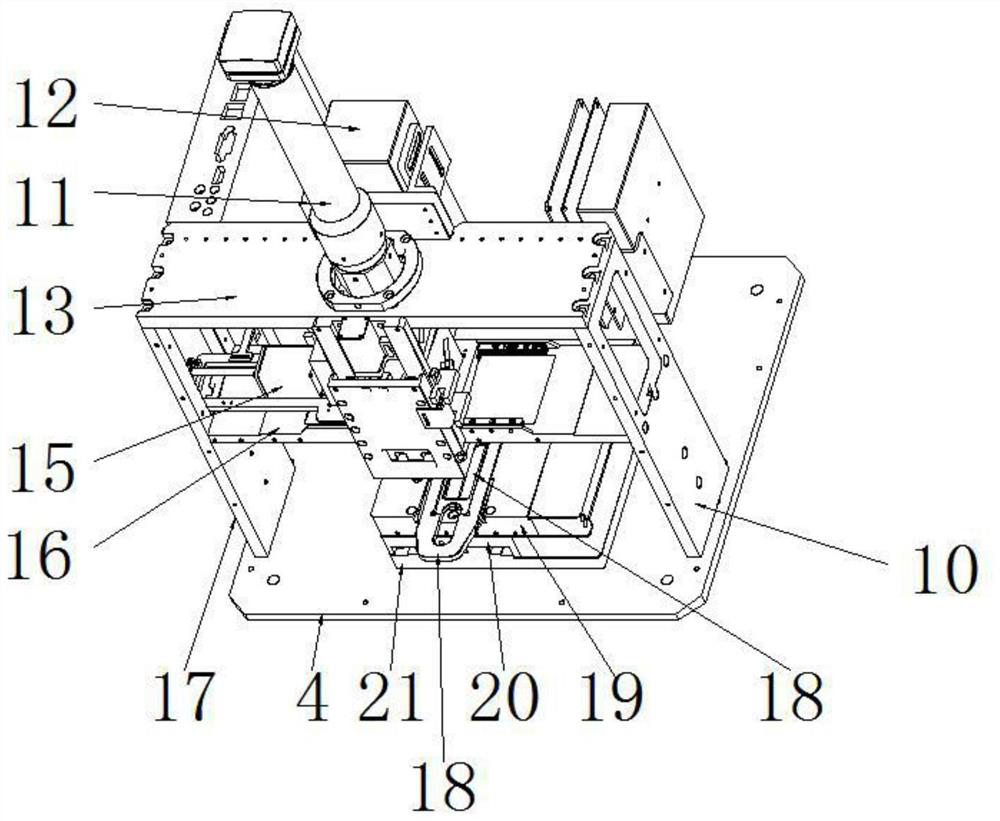
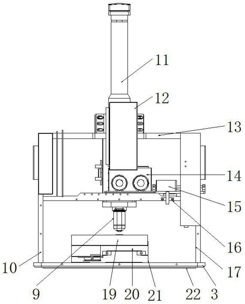
[0064] Specific implementation mode one, refer to Figure 1-10 , the present invention provides a technical solution: an automatic fluorescence scanning detection device and its method, comprising a lower body 3, the bottom of the lower body 3 is provided with a base plate 22, and the left end of the upper end surface of the base plate 22 is vertically fixed with a left fixing plate 17, And the upper end face right side of base plate 22 is vertically fixed with right fixed plate 10, is fixed with dividing plate 16 between the inner side middle part of left fixed plate 17 and the inner side middle part with right fixed plate 10, and left fixed plate 17 and right fixed plate The upper ends of the board 10 are respectively fixed vertically on the left and right ends of the bottom surface of the top plate 13. A microscopic imaging system 11 is installed in the middle of the top plate 13, and an automatic focusing system 12 is installed on the rear side of the middle part of the mic...

specific Embodiment approach 2

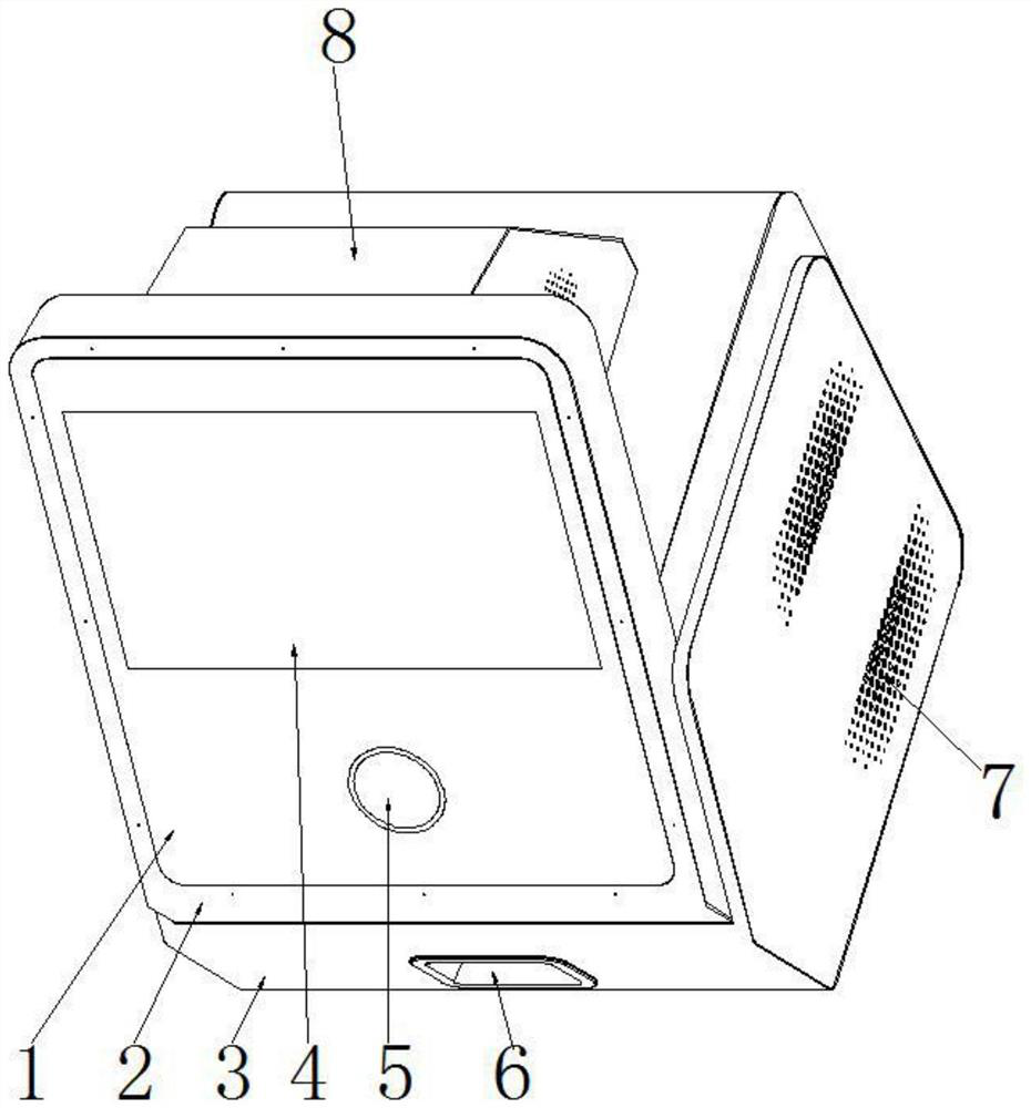
[0112] Embodiment 2. This embodiment is a further limitation of Embodiment 1. It mainly describes the external structure of the automatic fluorescence scanning detection equipment. The PC 1 in the present invention plays a role in controlling the microscope camera, focusing camera, power supply and The role of the device controller, so as to facilitate the display of scanning detection information on the touch screen 4, which is convenient for users to read intuitively.

specific Embodiment approach 3

[0113] Specific embodiment three, this embodiment is a further limitation to specific embodiment one, on the left and right sides of the lower body 3 are provided with cooling holes 7, the left and right sides of the top cover 8 are also provided with cooling holes, so that the cooling fan Air-cooled heat dissipation and ventilation are carried out to avoid excessive temperature of the internal structure of the equipment, so that the internal structure has a longer service life, and at the same time, it can avoid affecting the sample detection.


PUM


Abstract

The invention discloses automatic fluorescence scanning detection equipment and a method thereof. The equipment comprises a lower machine body, a bottom plate is arranged at the bottom of the lower machine body, a left fixing plate is vertically fixed to the left end of the upper end face of the bottom plate, and a right fixing plate is vertically fixed to the right end of the upper end face of the bottom plate; a partition plate is fixed between the middle of the inner side face of the left fixing plate and the middle of the inner side face of the right fixing plate, the upper end of the left fixing plate and the upper end of the right fixing plate are perpendicularly fixed to the left end and the right end of the bottom face of a top plate respectively, a microscopic imaging system is installed in the middle of the top plate, and an automatic focusing system is installed on the rear side of the middle of the microscopic imaging system. An objective lens imaging system is installed on the lower portion of the automatic focusing system, and the lower end of the objective lens imaging system faces a movable block on the movable platform structure. According to the automatic fluorescence scanning detection method, the operation steps of the equipment are introduced in detail, and each step is described more meticulously, so that a user can understand and operate more simply, and the equipment is more convenient to use.

Description

technical field [0001] The invention relates to the related technical field of fluorescence scanning detection, in particular to an automatic fluorescence scanning detection device and a method thereof. Background technique [0002] Fluorescence detection is a natural luminescence reaction, through the reaction of luciferase and ATP, it can detect human cells, bacteria, mold, and food residues. The reaction result is obtained within 15 seconds, and the illuminance is measured by special equipment and expressed in digital form. It was first applied in the food industry in 1975 and in the cosmetics manufacturing industry in 1985. [0003] The main disadvantage of fluorescence detection is that only a few compounds produce fluorescence, and most molecules do not fluoresce, but contain derivatizable functional groups for the synthesis of fluorescent derivatives. For example, o-phthalaldehyde is a commonly used fluorophore for Post-column derivatization of amino acids. Although...

Claims


Application Information

Patent Timeline
Patent Type & Authority Applications(China)
IPC IPC(8): G01N21/64G01N21/01G01N35/00
CPCG01N21/6458G01N21/01G01N35/00
Inventor 惠开进刘原仲苏明王文韬
Owner 苏州图墨医疗科技有限公司
Why Eureka
Try Eureka