Optimal dead zone calculation method and variable dead zone control method of high-frequency LLC resonant converter

A technology of resonant converter and calculation method, applied in control/regulation system, high-efficiency power electronic conversion, conversion of DC power input to DC power output, etc. Wide range, improved efficiency, reduced reverse conduction loss

Active Publication Date: 2021-06-18
HUAZHONG UNIV OF SCI & TECH
View PDF6 Cites 4 Cited by
  • Summary
  • Abstract
  • Description
  • Claims
  • Application Information

AI Technical Summary

Problems solved by technology

And as the operating frequency increases, the duty cycle of the dead time becomes larger, and the inappropriate dead time brings huge loss

Method used


Image

  • Optimal dead zone calculation method and variable dead zone control method of high-frequency LLC resonant converter
  • Optimal dead zone calculation method and variable dead zone control method of high-frequency LLC resonant converter
  • Optimal dead zone calculation method and variable dead zone control method of high-frequency LLC resonant converter

Examples


Embodiment Construction

[0043] In order to make the object, technical solution and advantages of the present invention clearer, the present invention will be further described in detail below in conjunction with the accompanying drawings and embodiments. It should be understood that the specific embodiments described here are only used to explain the present invention, not to limit the present invention. In addition, the technical features involved in the various embodiments of the present invention described below can be combined with each other as long as they do not constitute a conflict with each other.

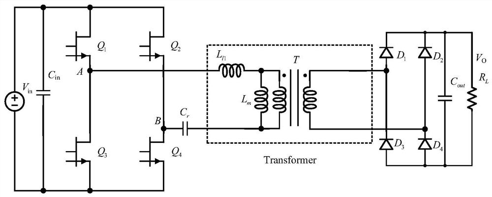
[0044] figure 1 is the topology diagram of the main circuit of the LLC resonant converter, where V in is the input DC voltage, C in is the input capacitance, Q 1 -Q 4 is a power MOS switch tube, r The transformer leakage inductance is also called resonant inductance, Cr is the resonant capacitor, L m is the exciting inductance, T is the transformer, N is the turn ratio of the transformer, ...


PUM


Abstract

The invention discloses a high-frequency LLC resonant converter optimal dead zone calculation method and a variable dead zone control method and belongs to the field of switching power supply digital control. Parasitic parameters of a power device under different working conditions are considered, the charging and discharging time of a parasitic capacitor of a primary side power tube is accurately calculated, and then the optimal dead zone time is obtained, so the parasitic capacitor of the power tube just completes charging and discharging in the optimal dead zone time, the time of reverse conduction of a cut-off state of the power tube is shortened, therefore, reverse conduction loss is reduced, efficiency of the high-frequency LLC resonant converter is improved, and the high-frequency LLC resonant converter can be suitable for LLC resonant converters with different power levels, different topological structures (full-bridge or half-bridge structures) and different resonant frequencies, and is wide in application range and high in reliability. When the method is applied to a resonant converter formed by a primary side power tube formed by a GaN MOSFET (Metal-Oxide-Semiconductor Field Effect Transistor), the reverse conduction loss can be obviously reduced, and along with the large-scale application of a GaN third-generation semiconductor device, the method has wide practical value.

Description

technical field [0001] The invention belongs to the field of digital control of switching power supplies, and more specifically relates to a method for calculating an optimal dead zone of a high-frequency LLC resonant converter and a method for controlling a variable dead zone. Background technique [0002] Under certain working conditions, the LLC resonant converter can not only realize zero-voltage turn-on (ZVS) on the primary side, but also realize zero-current turn-off (ZCS) on the secondary side, and is widely used in the field of switching power supplies. According to the gain characteristics of LLC, pulse frequency modulation (PFM) control is generally used, and dead time is added to the upper and lower power tubes to prevent short circuits. The time period for realizing the ZVS of the primary side is the first period of the dead time, and the charging and discharging of the parallel connection capacitors of all bridge arm tubes are completed through the resonant indu...

Claims


Application Information

Patent Timeline
Patent Type & Authority Applications(China)
IPC IPC(8): H02M3/335
CPCH02M3/33569Y02B70/10
Inventor 童乔凌姜宇航闵闰李林凯李启东
Owner HUAZHONG UNIV OF SCI & TECH
Why Eureka
Try Eureka