
Anti-scour construction method for offshore wind power pile foundation based on solidified side bulldozing

A construction method and technology for offshore wind power, which are applied in wind power generation, infrastructure engineering, sheet pile walls, etc., can solve the problems of high wind power foundation installation cost, complicated construction, and high riprap cost, and reduce the construction period and complexity. The effect of saving offshore operation time and improving economic efficiency

Inactive Publication Date: 2021-06-22
ZHEJIANG UNIV +1
View PDF11 Cites 6 Cited by
  • Summary
  • Abstract
  • Description
  • Claims
  • Application Information

AI Technical Summary

Problems solved by technology

But its disadvantage is that due to the influence of seabed topography and water flow, there is a greater risk of failure, and the pile foundation structure gradually increases, resulting in higher cost of riprap
Active anti-scouring usually installs anti-scouring devices outside the pile foundation, and achieves the purpose of anti-scouring by changing the water flow form in the anti-scouring area. This type of device has complex construction, high engineering cost, and adaptability to complex water flow conditions on the seabed Small, difficult to achieve comprehensive protection
In addition, the traditional anti-scouring method needs to be carried out after the pile foundation is installed. The long construction period makes the offshore construction time longer, resulting in high installation costs for wind power foundations and slow progress.
[0004] At present, the existing anti-scouring method ignores the weakening effect of the construction on the stress strength of the soil around the pile foundation during the installation process and lacks a close connection with the seabed soil. Offshore wind power anti-scour method against body disturbance is particularly important

Method used


Image

  • Anti-scour construction method for offshore wind power pile foundation based on solidified side bulldozing
  • Anti-scour construction method for offshore wind power pile foundation based on solidified side bulldozing
  • Anti-scour construction method for offshore wind power pile foundation based on solidified side bulldozing

Examples


Embodiment Construction

[0025] In describing the present invention, it is to be understood that the terms "one end", "the other end", "outer side", "upper", "inner side", "horizontal", "coaxial", "central", "end ", "length", "outer end" and other indicated orientations or positional relationships are based on the orientations or positional relationships shown in the drawings, which are only for the convenience of describing the present invention and simplifying the description, rather than indicating or implying the referred device or Elements must have certain orientations, be constructed and operate in certain orientations, and therefore should not be construed as limitations on the invention.

[0026] The present invention will be further described below in conjunction with accompanying drawing.

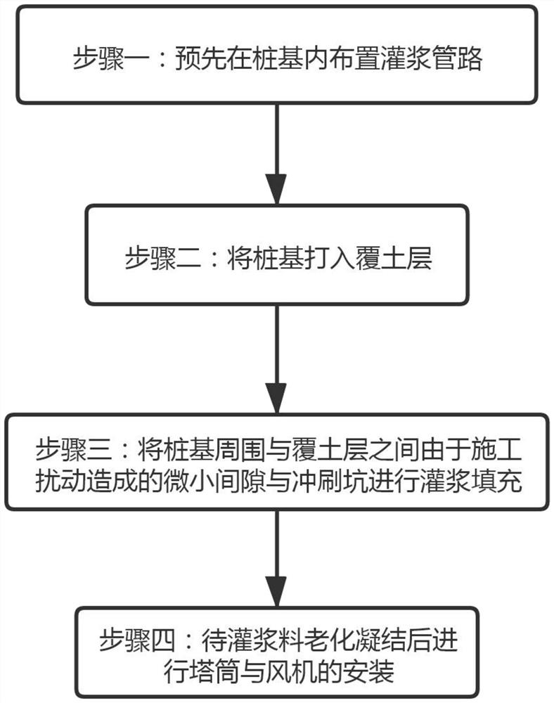
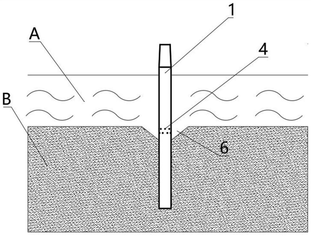
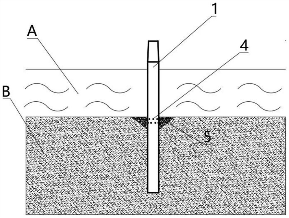
[0027] As shown in the figure, an anti-scour construction method for offshore wind power pile foundations based on solidified lateral bulldozing includes the following steps:

[0028] Step 1: arranging ...


PUM


Abstract

The invention belongs to the field of offshore wind power engineering, and particularly relates to an anti-scour construction method for an offshore wind power pile foundation based on solidified side bulldozing. The anti-scour construction method comprises the following steps that S1, a grouting pipeline is arranged in the pile foundation in advance; S2, the pile foundation is driven into an overburden layer; and S3, grouting equipment is connected with the grouting pipeline, and grouting filling is conducted on a scouring pit and a small gap caused by construction disturbance between the periphery of the pile foundation and the overburden layer till the upper surface of a grouting material is higher than the surface of the seabed overburden layer. The anti-scour construction method has the advantages that after the pile foundation is sunk, the gap between soil bodies around a pile and the scouring pit are grouted, soil body looseness generated in the installation process can be repaired, soil body holes can be filled, and therefore the bearing capacity of the pile foundation is prevented from being reduced, and the scouring pit is prevented from being further enlarged.

Description

technical field [0001] The invention belongs to the field of offshore wind power engineering, and in particular relates to an anti-scouring construction method for offshore wind power pile foundations based on solidified lateral bulldozing. Background technique [0002] As a renewable green energy, offshore wind power has attracted more and more attention. Offshore wind power generation has been widely used due to its advantages such as high energy density, limited by geographical environment factors, and large total hours of power generation. Local erosion of offshore wind power foundation is a problem faced by the development of offshore wind power. The marine meteorological and hydrological conditions in which offshore wind turbines are located are complex and changeable, and extreme waves and current sea conditions occur frequently. The sediment near the column is easy to move, which makes the foundation structure bare. On the one hand, this reduces the bearing capacit...

Claims


Application Information

Patent Timeline
Patent Type & Authority Applications(China)
IPC IPC(8): E02D31/06E02D27/42E02D27/52E02D5/50E02D15/04F03D13/25F03D13/10
CPCE02D5/50E02D15/04E02D27/42E02D27/52E02D31/06E02D2250/003F03D13/10F03D13/22F03D13/25Y02E10/72Y02E10/727
Inventor 朱嵘华马培宇王恒丰孙香刘寒秋涂智圣徐清富
Owner ZHEJIANG UNIV
Learn More