Pneumatic valve for inhibiting back pressure of air-breathing pulse detonation engine

A pulse detonation and engine technology, applied in the direction of machine/engine, mechanical equipment, climate sustainability, etc., can solve the problems of large mass, forward flow resistance and one-way control ability cannot be solved at the same time, complex structure, etc. Reduce adverse effects, eliminate adverse effects, avoid the effect of periodic changes in flow resistance

Active Publication Date: 2021-06-22
NORTHWESTERN POLYTECHNICAL UNIV
View PDF8 Cites 2 Cited by
  • Summary
  • Abstract
  • Description
  • Claims
  • Application Information

AI Technical Summary

Problems solved by technology

In order to solve these problems, the present invention proposes a pneumatic valve for suppressing the back pressure of the air-breathing pulse detonation engine, which overcomes the shortcomings of the mechanical valve type, such as complex structure, large mass, and periodic flow resistance changes, and improves the existing pneumatic valve. The problem that the forward flow resistance and one-way control ability of the valve structure cannot be solved at the same time, while having a high anti-backpressure ability in a short radial length, it also ensures a high recovery coefficient of the total intake pressure

Method used


Image

  • Pneumatic valve for inhibiting back pressure of air-breathing pulse detonation engine
  • Pneumatic valve for inhibiting back pressure of air-breathing pulse detonation engine
  • Pneumatic valve for inhibiting back pressure of air-breathing pulse detonation engine

Examples


Embodiment Construction

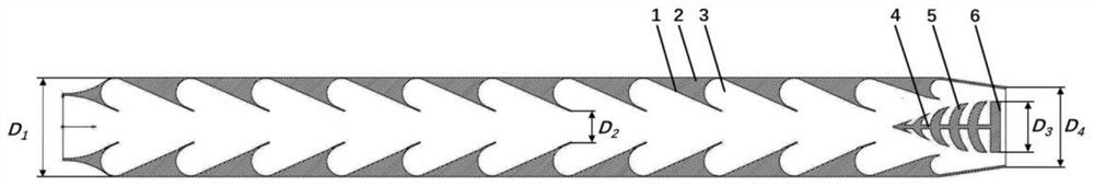
[0035] The pneumatic valve proposed in inhibiting the inhalation pulse explosion engine inhibition, the main structure includes: a back pressure suppression section cover, a central cone.

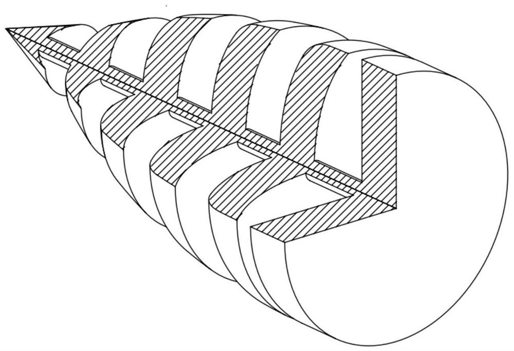
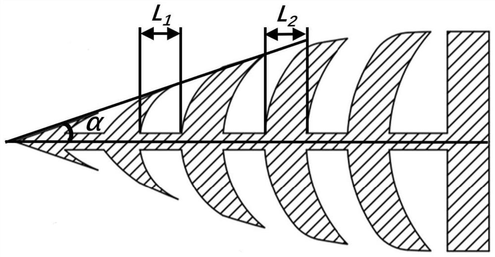
[0036] Such as figure 2 with image 3As shown, the central cone one end has a planar disc, which can be used to act as a thrust wall of the knock chamber; further a central axis and a plurality of curved discs mounted on the central axis, these arc circles The front and rear end faces of the disk are the curved surface; the center axis passes the center of these curved discs, and the edges of these curved discs are on conical surfaces of the cone 2 alpha, and the concave surface of the curved disc is oriented as a thrust wall. Plane disc. The preferred α angle is no more than 45 °, and further preferably takes 12.5 °.

[0037] In the present invention, the central thickness of these curved discs and the central axis connection position is L. 2 However, the central axis length between adjacent cu...


PUM


Abstract

The invention provides a pneumatic valve for inhibiting back pressure of an air-breathing pulse detonation engine, comprising a back pressure inhibiting section outer cover and a center cone. Compared with a mechanical valve, the flow resistance periodic change caused by opening and closing of the valve can be avoided, and the flow pressure loss is reduced; and compared with an existing pneumatic valve type structure, the problem that the high back pressure resistance and the high air inlet total pressure recovery coefficient cannot be achieved at the same time is solved. When pressure is transmitted back, pressure waves transmitted back to the upstream are weakened through a gap between discs, and therefore pressure pulsation is reduced, stable work of the air-breathing pulse detonation engine is facilitated, and the propelling performance is improved. According to the back pressure inhibiting section outer cover, most of incoming flow flows along the central axis, and the pressure loss is small. When the pressure is reversely transmitted, the pressure waves are transmitted in two directions of the axis and the annular cavity, and the pressure waves transmitted to the upstream can be weakened, so that the adverse effect of periodical reverse transmission pressure on upstream components can be reduced and eliminated, and stable work of the air-breathing pulse detonation engine is facilitated.

Description

Technical field [0001] The present invention relates to the field of engine technology, and more particularly to a pneumatic valve that suppresses the inhalation pulse explosion engine. Background technique [0002] The intake pulse explosion engine is a power device for obtaining thrust using a high temperature and high pressure gas generated by a batch or pulsed knock wave. The pulse explosion cycle has the characteristics of high thermal cycle efficiency, low unit fuel consumption, wide working and low pollution. The intake pulse explosion engine is divided into two major categories: "pure" suction pulse burst engine and pulse buffer turbine engine. Among them, the "pure" pulse explosive engine is generally composed of an intake passage, a knock chamber, and a nozzle, which directly uses the high-temperature high-pressure product of the knock chamber to be thrown out of the high speed of the tail nozzle. Pulse buffer turbine engine is a new engine in a conventional turbine eng...

Claims


Application Information

Patent Timeline
IPC IPC(8): F02K7/067F02K7/02
CPCF02K7/067F02K7/02Y02T50/60
Inventor 王治武杨予煊伟力斯张隆飞王亚非
Owner NORTHWESTERN POLYTECHNICAL UNIV
Why Eureka
Try Eureka