
Drilling device for soil detection

A drilling device and soil detection technology, applied in the direction of sampling devices, etc., can solve the problems that the drilling direction is difficult to ensure vertical, affect the normal operation, and cannot be used by hand, so as to achieve a scientific and reasonable power transmission structure and improve the drilling efficiency. Efficiency, ease of use and flexible effects

Pending Publication Date: 2021-06-22
江居燕
View PDF0 Cites 0 Cited by
  • Summary
  • Abstract
  • Description
  • Claims
  • Application Information

AI Technical Summary

Problems solved by technology

[0003] First, before the drilling operation starts, the equipment needs to be erected manually on the ground, and the relatively heavy main engine must be lifted to a high position. During the drilling operation, the main engine needs to be manually supported. After the drilling is completed, the entire equipment needs to be lifted. The entire operation process is relatively laborious and often cannot be operated by one person to remove the drill pipe from the hole.
[0004] Second, the direction of the drill pipe is usually controlled by the operator holding the main engine by hand. It is difficult to ensure that the drilling direction is vertical, which often affects the normal operation of subsequent operations.
[0005] Its three, the existing soil detection drilling device is based on its hand-held structural design characteristics, and a single drill rod should not be too long, otherwise it cannot be used hand-held. The rods are fixedly connected in turn, and the connection operation between the drill rod and the drill rod, and between the drill rod and the main engine is relatively troublesome

Method used


Image

  • Drilling device for soil detection
  • Drilling device for soil detection
  • Drilling device for soil detection

Examples


Embodiment 1

[0037] The drilling device for soil detection disclosed in this embodiment is composed of two parts: a main engine and a drilling tool that work together;

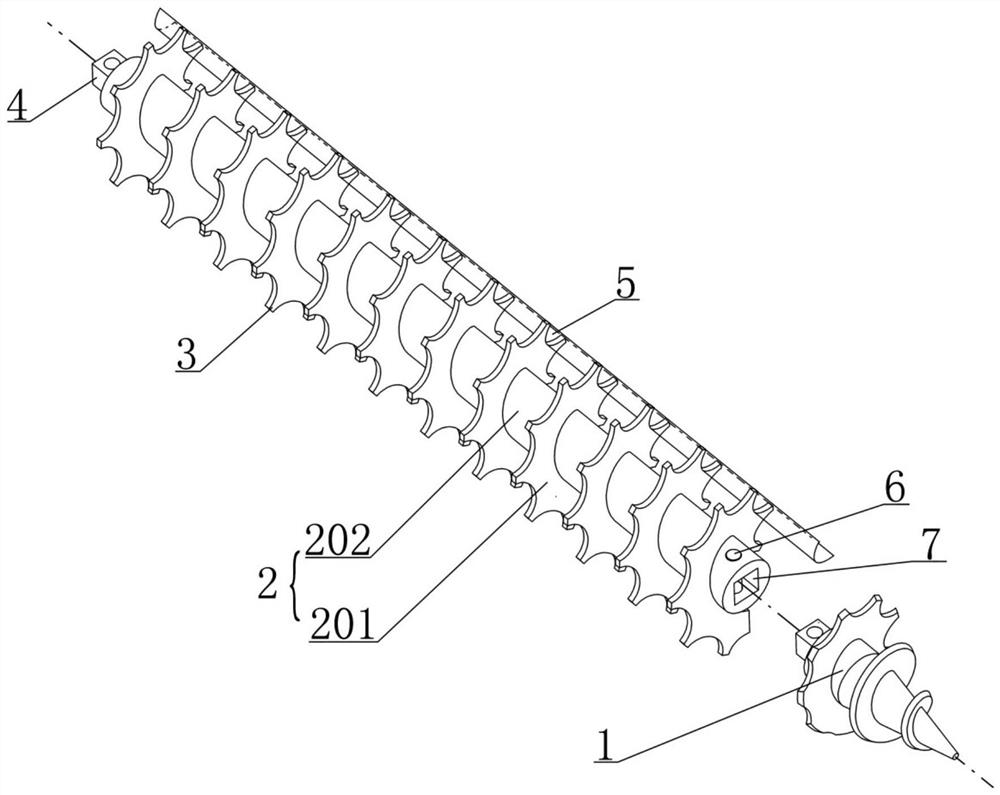
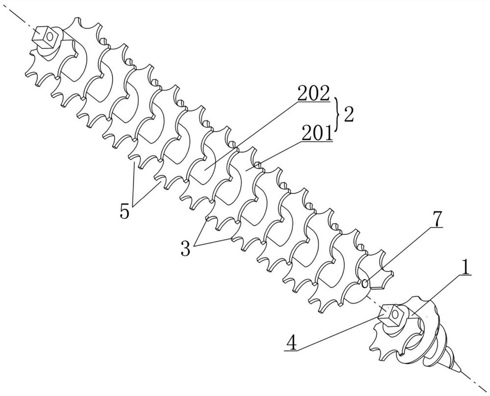
[0038] Among them, see figure 1 , 2 As shown, the drilling tool includes a drill bit 1 and a drill rod 2 that can be combined and connected. There are multiple drill rods 2 that can be connected end to end; the drill rod 2 is composed of a core rod 202 and a helical piece 201. The sheet 201 is wound and fixed on the outside of the core rod 202; the helical sheet 201 is surrounded by a number of axial grooves 5 that are equiangularly distributed and extend axially along the drill pipe 2, and the outer edge of the helical sheet 201 is in the adjacent axial groove. The part between 5 is tooth 3;

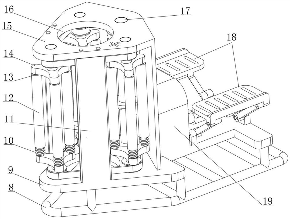
[0039] Among them, see Figure 3-6As shown, the main engine includes a frame 8, and the frame 8 is provided with a top plate 15 and a bottom plate 9 distributed up and down. The bottom plate 9 has a ground clearance after the fra...

Embodiment 2

[0063] see Figure 11 As shown, during the drilling operation of the drilling device for soil testing disclosed in the aforementioned embodiments, the spiral piece 201 will transport the soil material produced by the drilling to the ground. Generally, it will not affect the normal operation of the drilling operation. If the drilling depth is deep and there is a lot of soil material, it is necessary to transfer the soil material to avoid the accumulation of soil material above the hole and affect the drilling efficiency. The soil material produced by drilling can be transferred by tools such as shovels to avoid the accumulation of soil material above the hole, but this operation method is cumbersome, time-consuming and laborious. For this reason, this embodiment has further improvements on the basis of the structure of the drilling device for soil detection disclosed in Embodiment 1, and the specific structure is:

[0064] see Figure 14 , 15 As shown, the lower end of the r...

Embodiment 3

[0068] see Figure 11 As shown, in the structure adopted by the drilling device for soil detection disclosed in the foregoing embodiments, the helical piece 201 is provided with an axial groove 5 so that its outer end is formed with teeth 3 distributed at intervals, and the helical piece 201 This special structure will weaken its upward conveying ability to soil materials, but because most of the soil at the sampling site has poor fluidity, in addition, parts such as the slewing frame 14, the dial roller 12, the axial groove 5, and the teeth 3 can be adjusted during implementation. The parameters such as the relative positional relationship, quantity, specific shape, and size of each hole are reasonably adjusted to make up for the aforementioned insufficient conveying capacity, thereby ensuring that the spiral blade 201 can convey the soil material produced during the drilling process to the ground above. At the same time, this embodiment has a further improvement on the basis...


PUM


Abstract

The invention relates to the field of soil detection tools, and particularly discloses a drilling device for soil detection. The drilling device consists of a main machine and a drilling tool, wherein the drilling tool comprises a drilling rod, a spiral piece is arranged on the drilling rod, and teeth are evenly distributed on the periphery of the spiral piece; the main machine is internally provided with a plurality of rotary frames, a main shaft, a transmission shaft and a driving shaft which are sequentially in transmission connection, each rotary frame is provided with a plurality of roller shafts, the roller shafts are sleeved with stirring rollers, the driving shaft is provided with a pedal, after the drilling tool is combined with the main machine, the pedal can be treaded to drive the rotary frames to rotate, when the rotary frames rotate, the stirring rollers on the rotary frames circularly stir the teeth to jointly drive the drill rod to rotate, and then the drill rod is driven to drill downwards. The drilling device for soil detection is scientific and reasonable in structure, high in utilization rate of mechanical parts, small in energy loss, flexible and convenient to use, efficient and labor-saving in operation, large in drilling depth range and high in practicability, and has wide application prospects in soil detection.

Description

technical field [0001] The invention relates to a soil detection tool, in particular to a drilling device commonly used in the soil detection and sampling process. Background technique [0002] In the practice of soil environment monitoring and agricultural planting production, it is often necessary to test and analyze the soil at a specific depth to understand the soil pollution degree or composition parameters of the soil. At this time, it is usually necessary to use a drilling device to drill holes in the soil , to place a soil sensor or to sample soil at a specific depth. At present, the commonly used drilling devices for soil testing mostly adopt the hand-held design, which is composed of a drill pipe with helical fins and a main engine with power. Since the main engine is equipped with a motor or a fuel engine, the whole equipment is relatively heavy and not light enough to be used conveniently. , poor portability, although the motor or engine is used as the power sou...

Claims


Application Information

Patent Timeline
IPC IPC(8): G01N1/08
CPCG01N1/08
Inventor 江居燕
Owner 江居燕
Learn More