Patch magnetic element and manufacturing method thereof
A magnetic component and patch technology, which is applied in the manufacture of inductors/transformers/magnets, electrical components, inductors with magnetic cores, etc., can solve problems such as crossover of inductive and outgoing lines, interference from peripheral devices, and poor high-frequency characteristics. Achieve the effects of small DC resistance, improved reliability, and high Q value characteristics
- Summary
- Abstract
- Description
- Claims
- Application Information
AI Technical Summary
Problems solved by technology
Method used
Image
Examples
Embodiment 1
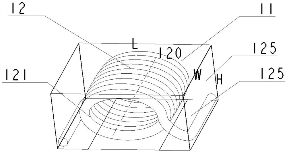
[0064] The structural perspective view of this embodiment is as figure 1 As shown, a patch magnetic component has a length L≥width W≥height H, including: a coil winding 12 whose winding axis 120 is parallel to the width W direction of the magnetic component, and the winding has two ends connected to two terminals 125; the body 11 is included around the coil winding 12; the terminals 125 are distributed along the length L direction on the left and right sides of the winding axis 120, and the terminal electrodes 125 are located on the bottom and side surfaces in this embodiment;
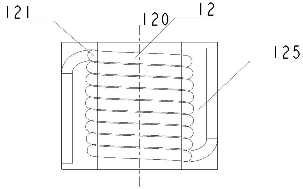
[0065] The shape of the coil winding 12 is elliptical, and the coil winding 12 has a curved warping part 121 in the length L direction of the left and right sides of the winding axis 120; figure 2 As shown, the coil winding 12 satisfies that at least part of it falls in the terminal area 125 in the bottom LW plane projection. It can be seen from the figure that the arc warping part 121 basically falls...
Embodiment 2
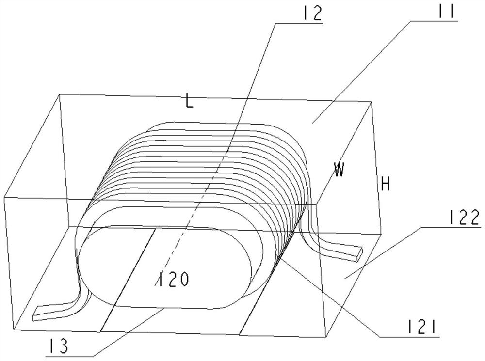
[0067] The structural perspective view of this embodiment is as image 3 As shown, a patch magnetic element, its length L≥width W≥height H, includes: coil winding 12, its winding axis 120 is parallel to the width W direction of the magnetic element, and the winding has two ends connected to two copper The terminals 122 are connected by spot welding or thermocompression welding; the body 11 is included around the coil winding 12; the terminals 122 are distributed along the length L direction on the left and right sides of the winding axis 120, and the terminal electrodes in this embodiment 122 position is on the bottom surface;
[0068] The shape of the coil winding 12 is a racetrack shape, and the coil winding 12 has a curved warping part 121 in the length L direction of the left and right sides of the winding axis 120; The magnetic element of this embodiment also includes a central column 13, the material of which is a sendust metal powder core; the coil winding is wound aro...
Embodiment 3
[0070] The appearance of this embodiment is as follows Figure 4 As shown, a chip inductance element is electroplated with terminal electrodes 125 on five sides on the body 11 . Its length L≥width W≥height H, such as Figure 5 As shown, it includes: a coil winding 12, the winding axis 120 of which is parallel to the width W direction of the magnetic element, and the winding has two ends connected to terminal electrodes 125; the body 11 is included around the coil winding 12; the The terminals 125 are distributed on the left and right sides of the winding axis 120 along the length L direction. In this embodiment, the terminal electrodes 125 are located on the upper and lower bottom surfaces and side surfaces.
[0071] The shape of the coil winding 12 is a racetrack shape, and the coil winding 12 has a curved warping part 121 in the length L direction of the left and right sides of the winding axis 120; The magnetic element of this embodiment also includes a central column 13,...
PUM
 Abstract
Description
Claims
Application Information
 - R&D
- Intellectual Property
- Life Sciences
- Materials
- Tech Scout
- Unparalleled Data Quality
- Higher Quality Content
- 60% Fewer Hallucinations
Browse by: Latest US Patents, China's latest patents, Technical Efficacy Thesaurus, Application Domain, Technology Topic, Popular Technical Reports.
© 2025 PatSnap. All rights reserved.Legal|Privacy policy|Modern Slavery Act Transparency Statement|Sitemap|About US| Contact US: help@patsnap.com


