
Photovoltaic automatic cleaning support system

An automatic cleaning and support system technology, applied in photovoltaic modules, photovoltaic power generation, cleaning methods and appliances, etc., can solve the problems of component power generation efficiency discount, system power generation reduction, and low work efficiency, so as to reduce cleaning difficulty and save Resource and energy saving effects

Inactive Publication Date: 2021-06-25
GUANGDONG SOLARSTOCK NEW ENERGY TECH
View PDF1 Cites 0 Cited by
  • Summary
  • Abstract
  • Description
  • Claims
  • Application Information

AI Technical Summary

Problems solved by technology

[0002] With the large-scale development and application of the photovoltaic industry, the post-maintenance of photovoltaic power generation systems and the improvement of photovoltaic power generation efficiency have gradually become the focus of attention. Dust and other stains on the surface of photovoltaic modules have become one of the main factors affecting the smooth and efficient operation of photovoltaic power generation systems. First, although photovoltaic modules can self-clean through rainfall, in some dusty environments, the power generation efficiency of the modules will be greatly reduced, resulting in a reduction in system power generation and huge losses
However, most of the existing photovoltaic cleaning methods use manual cleaning. Manual cleaning of photovoltaic modules is labor-intensive, time-consuming and labor-intensive, and the work efficiency is low.

Method used


Image

  • Photovoltaic automatic cleaning support system
  • Photovoltaic automatic cleaning support system
  • Photovoltaic automatic cleaning support system

Examples


Embodiment Construction

[0027] The following will clearly and completely describe the technical solutions in the embodiments of the present invention with reference to the accompanying drawings in the embodiments of the present invention. Obviously, the described embodiments are only some, not all, embodiments of the present invention. Based on the embodiments of the present invention, all other embodiments obtained by persons of ordinary skill in the art without making creative efforts belong to the protection scope of the present invention.

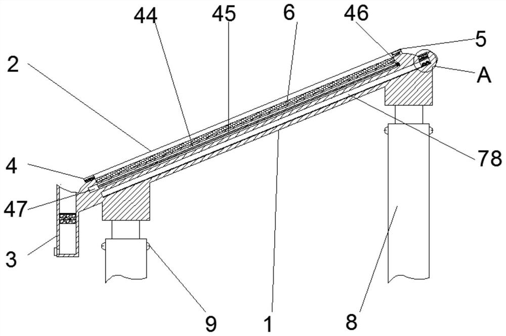
[0028] see Figure 1~6 , in the embodiment of the present invention, the photovoltaic automatic cleaning support system includes a support body 1, a telescopic rod 8 is fixedly installed at the lower end of the support body 1, and the telescopic rod 8 is installed at the four corners of the lower end of the support body 1, and the middle part of the telescopic rod 8 is provided with a There are fixed limit bolts 9, the upper end of the support body 1 is symmet...


PUM


Abstract

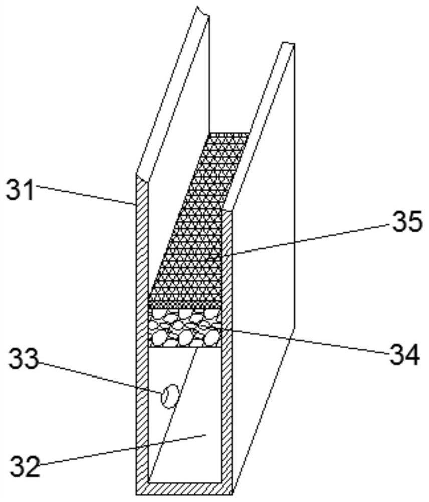
The invention discloses a photovoltaic automatic cleaning support system. The photovoltaic automatic cleaning support system comprises a support body, wherein telescopic rods are fixedly installed at the lower end of the support body, the telescopic rods are installed at the four corners of the lower end of the support body, and fixing limiting bolts are arranged at the telescopic positions of the middles of the telescopic rods; limiting supports are symmetrically and fixedly installed on the left side and the right side of the upper end of the support body, a built-in photovoltaic assembly is fixed in the middle of the upper end of the support body, and a filtering and recycling device is fixedly installed at the front end of the support body; and the filtering and recycling device comprises a recycling water tank, a recycling tank inner cavity, a recycling opening, a filtering layer and a grid plate, the recycling tank inner cavity is formed in the recycling water tank, the recycling opening is fixedly formed in the lower middle side of the front end of the recycling water tank, and the recycling opening communicates with the recycling tank inner cavity. When the photovoltaic automatic cleaning support system is used, the cleaned water flow flows into the recycling water tank through the obliquely-arranged supports on the upper side, large-scale impurity screening is carried out through the grid plate, then foreign matter such as bacteria is filtered through activated carbon and flows into the recycling water tank, subsequent recycling is carried out, and resources are saved.

Description

technical field [0001] The invention relates to the technical field of new energy, in particular to a photovoltaic automatic cleaning support system. Background technique [0002] With the large-scale development and application of the photovoltaic industry, the post-maintenance of photovoltaic power generation systems and the improvement of photovoltaic power generation efficiency have gradually become the focus of attention. Dust and other stains on the surface of photovoltaic modules have become one of the main factors affecting the smooth and efficient operation of photovoltaic power generation systems. First, although photovoltaic modules can self-clean through rainfall, in some dusty environments, the power generation efficiency of the modules will be greatly reduced, resulting in a reduction in system power generation and huge losses. However, most of the existing photovoltaic cleaning methods use manual cleaning, which is labor-intensive, time-consuming and labor-int...

Claims


Application Information

Patent Timeline
Patent Type & Authority Applications(China)
IPC IPC(8): B08B1/00B08B3/02B08B3/14F26B21/00F26B23/06H02S40/10
CPCB08B3/02B08B3/14F26B23/06F26B21/001H02S40/10B08B1/30B08B1/12Y02E10/50
Inventor 王宁钢陈云华
Owner GUANGDONG SOLARSTOCK NEW ENERGY TECH
Learn More