Metal composite plate rolling method capable of strengthening deformation behavior of bonding interface

A metal composite plate, metal plate technology, applied in the direction of metal rolling, metal rolling, metal processing equipment, etc., can solve the problem of low bonding strength of the metal composite plate interface, to reduce adverse effects, improve bonding strength, ensure The effect of shape accuracy

Pending Publication Date: 2021-06-25
TAIYUAN UNIV OF TECH
View PDF7 Cites 3 Cited by
  • Summary
  • Abstract
  • Description
  • Claims
  • Application Information

AI Technical Summary

Problems solved by technology

[0004] The invention aims to solve the technical problem of low interface bonding strength of the metal composite plate made by the existing rolling method

Method used


Image

  • Metal composite plate rolling method capable of strengthening deformation behavior of bonding interface
  • Metal composite plate rolling method capable of strengthening deformation behavior of bonding interface
  • Metal composite plate rolling method capable of strengthening deformation behavior of bonding interface

Examples


Embodiment 1

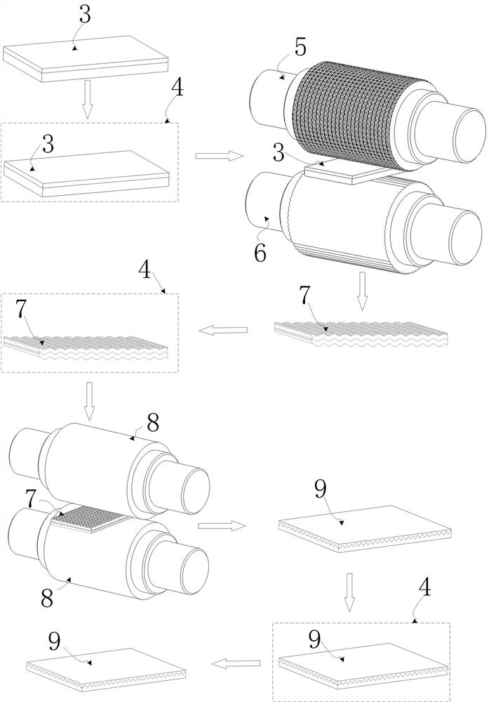
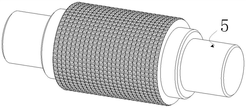
[0024] refer to Figure 1-7 , a Cu / Al clad plate rolling method capable of strengthening bonding interface deformation behavior, comprising the following steps:

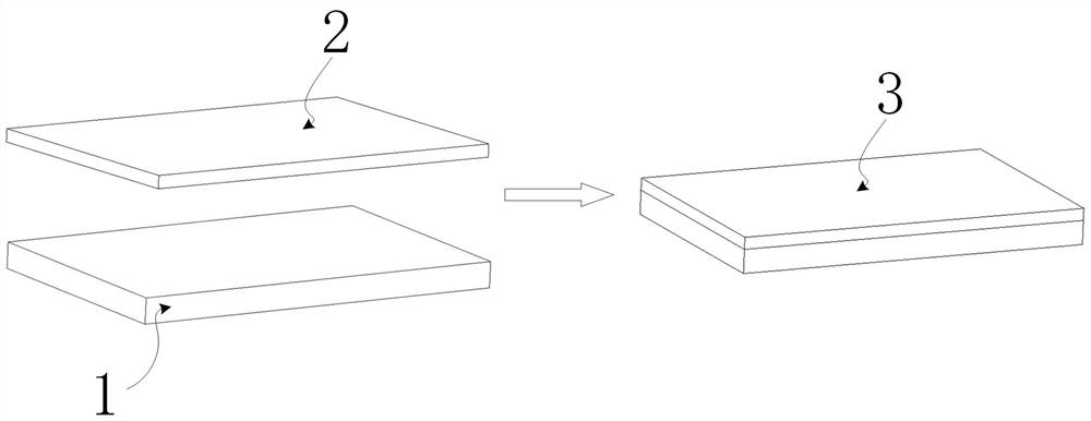
[0025] S1. Blank making: Al plate with relatively small deformation resistance is selected as substrate 1, and the length, width and height are 50mm, 50mm, and 3mm respectively, and Cu with relatively large deformation resistance is selected as double plate 2, and the length, width, and height are 50mm and 50mm respectively , 1mm, the thickness ratio of the substrate 1 and the doubler board 2 is 3, use a wire brush to polish the surface of the substrate 1 and the doubler board 2 to be bonded, remove the surface oxide layer and pollutants, and stack the doubler boards 2 on the front of the substrate 1 Press the top and fix the edges (to ensure that the base plate 1 and double plate 2 will not be misaligned and deviated when they are subjected to non-uniform tangential force during the rolling process), and the metal c...

Embodiment 2

[0031] refer to Figure 1-7 , a Cu / Al clad plate rolling method capable of strengthening bonding interface deformation behavior, comprising the following steps:

[0032] S1. Blank making: Al plate with relatively small deformation resistance is selected as the substrate 1, and the length, width and height are 50, 50, and 3 mm respectively, and Cu with relatively large deformation resistance is selected as the doubler plate 2, and the length, width, and height are 50, 50 mm, respectively. , 1mm, the thickness ratio of the substrate 1 and the doubler board 2 is 3, use a wire brush to polish the surface of the substrate 1 and the doubler board 2 to be bonded, remove the surface oxide layer and pollutants, and stack the doubler boards 2 on the front of the substrate 1 Press the top and fix the edges (to ensure that the base plate 1 and double plate 2 will not be misaligned and deviated when they are subjected to non-uniform tangential force during the rolling process), and the met...


PUM


Abstract

The invention relates to the technical field of metal composite plate preparation, and particularly relates to a metal composite plate rolling method capable of strengthening the deformation behavior of a bonding interface. The metal composite plate rolling method aims to solve the technical problem that the interface bonding strength of a metal composite plate prepared by adopting an existing rolling method is low. According to the technical scheme, a corrugated roller rolling mill is adopted for rolling a base plate and a composite plate in the first pass, wherein an upper roller adopts a crossed corrugated roller, a lower roller adopts a one-way corrugated roller with one-way corrugations, and the metal composite plate with the upper surface being a crossed corrugated surface, the lower surface being a one-way corrugated surface and the bonding interface being a complex crossed corrugated surface can be obtained; and a flat roller rolling mill is adopted for rolling the upper surface and the lower surface flat in the second pass. Compared with a traditional rolling method, the rolling process of the method is simple, the deformation behavior of the bonding interface of the metal composite plate can be strengthened by using the corrugated roller rolling mill, diffusion of two metal atoms is promoted to a greater extent, firm bonding is formed, warping of the plate can be reduced, and edge cracking can be inhibited.

Description

technical field [0001] The invention relates to the technical field of metal composite plate preparation, in particular to a metal composite plate rolling method that can strengthen the deformation behavior of the bonding interface. Background technique [0002] The metal composite panel is a composite material that is made of two or more layers of heterogeneous metals processed by a special process to achieve interfacial metallurgical bonding. After metallurgical bonding, the plate not only has the characteristics of wear resistance, corrosion resistance, oxidation resistance, and long service life, but also has excellent mechanical properties such as high strength, toughness, impact resistance, and stretchability. It can also save precious metal materials and reduce production costs. . Therefore, it is widely used in aerospace, petrochemical, shipbuilding, electric power, machinery manufacturing and other fields. In view of the perfect combination of low cost and high pe...

Claims


Application Information

Patent Timeline
Patent Type & Authority Applications(China)
IPC IPC(8): B21B1/38B21B47/00B21B45/00
CPCB21B1/38B21B47/00B21B45/004B21B2001/386
Inventor 冯光马晓宝郜豪杰张恒申依伦
Owner TAIYUAN UNIV OF TECH
Why Eureka
Try Eureka