
Cooling device for aeroengine turbine guide vane

A turbine guide, aero-engine technology, applied in engine components, machines/engines, mechanical equipment, etc., can solve problems such as limited air heat dissipation capacity, and achieve the effects of reducing instability, increasing combustion efficiency, and improving strength

Active Publication Date: 2022-06-28
BEIHANG UNIV
View PDF0 Cites 0 Cited by
  • Summary
  • Abstract
  • Description
  • Claims
  • Application Information

AI Technical Summary

Problems solved by technology

The traditional cooling methods mainly include film cooling, impingement cooling, divergent cooling, rib wall enhanced heat transfer, spoiler column enhanced heat transfer, etc. The cooling medium in the above cooling methods is air from the compressor or combustion chamber, but the air It is an indisputable fact that the cooling capacity of the

Method used


Image

  • Cooling device for aeroengine turbine guide vane
  • Cooling device for aeroengine turbine guide vane
  • Cooling device for aeroengine turbine guide vane

Examples


Embodiment Construction

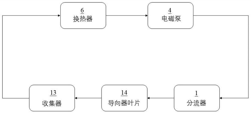
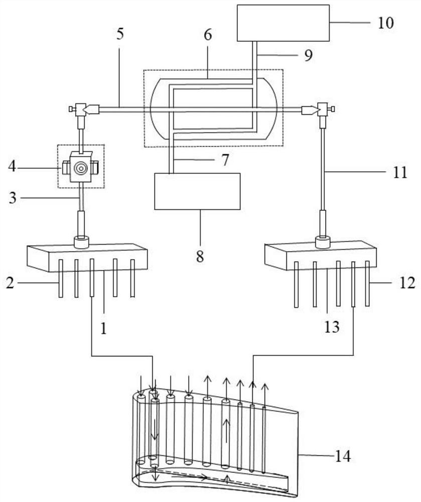
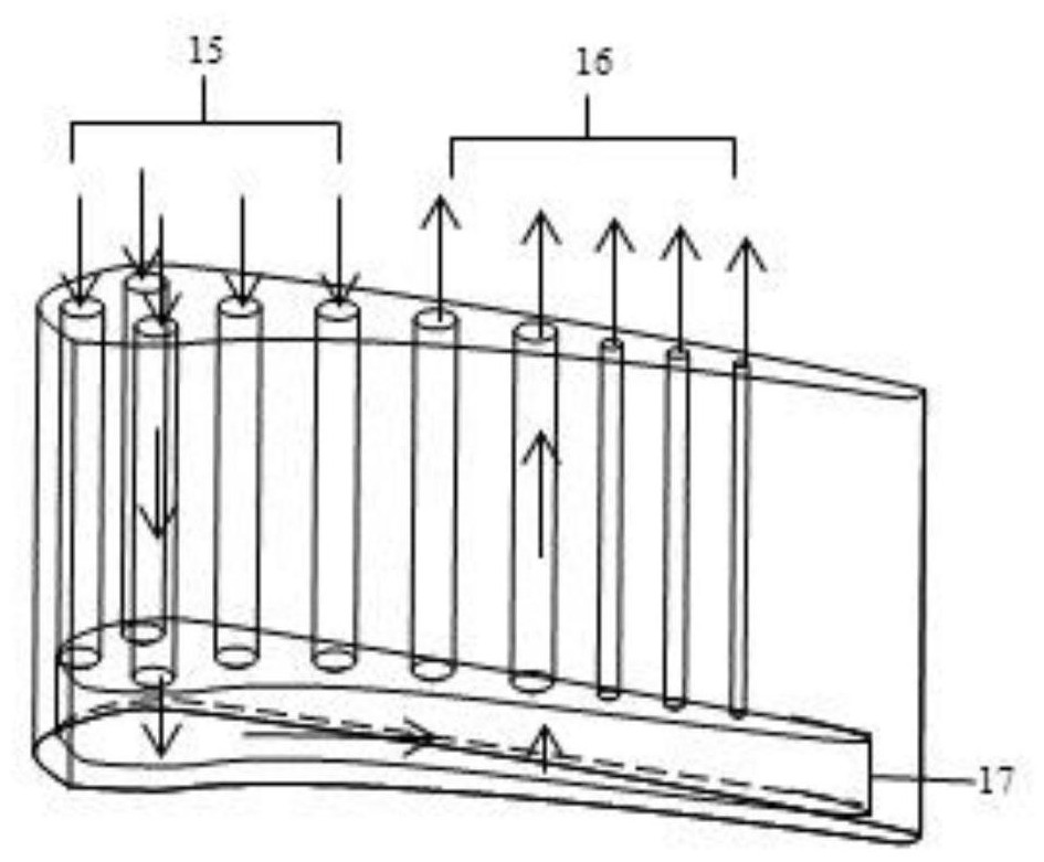
[0032] figure 1 is a schematic logic control diagram of a cooling device for a turbine guide vane of an aero-engine according to an embodiment of the present application. figure 2 It is a schematic structural diagram of a cooling device for aero-engine turbine guide vanes. image 3 is a schematic perspective view of the guide vane.

[0033] like image 3 As shown, in this embodiment, a plurality of cooling channels are arranged in the guide vane 14 according to the airfoil shape. A cavity 17 is reserved at the bottom position within the guide vane 14 . Each cooling channel communicates with the chamber 17 . Part of the cooling passages in the plurality of cooling passages are inflow blade cooling passages 15 , and the remaining cooling passages in the plurality of cooling passages are outflow blade cooling passages 16 . like figure 1 shown, see also Figure 2-3, this embodiment provides a cooling device for aero-engine turbine guide vanes using a low melting point meta...


PUM


Abstract

The application discloses a cooling device for an aeroengine turbine guide blade, and relates to the cooling of the guide blade. In this application, low-melting point metals or their alloys are used as the working medium, and multiple cooling passages and chambers are arranged in the guide blades. The cooling device includes flow dividers, collectors, heat exchangers and electromagnetic pumps, which form a closed loop with the guide blades. loop, the electromagnetic pump drives the working medium to circulate in the closed loop loop, and the heat is quickly dissipated through the heat exchanger. This application can reduce the instability caused by the mixing of cold and hot air; the application has excellent cooling effect and high heat exchange efficiency, which is beneficial to prolong the service life of the guide vane; this application can improve the strength of the guide vane and reduce the processing time. Process cost; this application preheats aviation kerosene in advance to improve its combustion efficiency; the entire process of this application is closed in cycle, low melting point metals or their alloys can be recycled repeatedly, and have no impact on the environment.

Description

technical field [0001] The present application relates to aero-engine turbine guide vanes, and in particular, to a cooling device for aero-engine turbine guide vanes. Background technique [0002] As the "heart" of the aircraft, the aero-engine is known as the "jewel in the industrial crown", and its performance indicators directly affect the safety, reliability and economy of the aircraft. In the development of aviation gas turbine engines, in order to improve the thermal efficiency and thrust-weight ratio of the engine, the boost ratio of the compressor and the inlet temperature of the turbine have been continuously increased. The engine with a thrust-to-weight ratio of 10 in the fourth-generation fighter has a compressor boost ratio of over 30, and the temperature before the turbine is close to 2000K. It is expected that a fighter engine with a thrust-to-weight ratio of more than 20 may appear around 2030. Compared with the F119 engine, the fuel consumption rate is reduc...

Claims


Application Information

Patent Timeline
Patent Type & Authority Patents(China)
IPC IPC(8): F01D9/02F01D25/12
CPCF01D9/02F01D25/12
Inventor 罗翔张哲邬泽宇
Owner BEIHANG UNIV
Learn More