Image acquisition system and image acquisition method
An image and image synthesis technology, applied in image memory management, size/direction of magnetic field, acquisition/recognition of microscopic objects, etc., can solve problems such as limiting the shape of the sample, unable to understand the frequency of strain, unable to grasp the state of strain distribution, etc.
- Summary
- Abstract
- Description
- Claims
- Application Information
AI Technical Summary
Problems solved by technology
Method used
Image
Examples
Embodiment 1
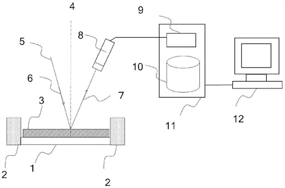
[0057] refer to figure 1 The configuration of the image acquisition system of the first embodiment will be described.
[0058] The image acquisition system includes a sample stage mechanism system, an optical system and an image processing system.
[0059] The sample stage mechanism system includes: a sample holder (holder) 1 including a sample stage that fixes a magnetic sample 3 and can move in the XYZ axes; and an electromagnetic coil 2 that can apply an external magnetic field. The optical system has a detector 8 . The image processing system has a control device 11 and an image display terminal (GUI) 12 . The control device 11 has a signal processing unit 9 and a storage unit (database) 10 .
[0060] Laser light 5 is incident on the plane of sample 3 as incident light 6 , and incident light 7 reflected on the plane of sample 3 is detected by detector 8 . Here, 4 denotes the sample normal direction. The detection signal detected by the detector 8 is sent to the signal...
Embodiment 2
[0092] refer to Figure 8 The image acquisition method of the second embodiment will be described.
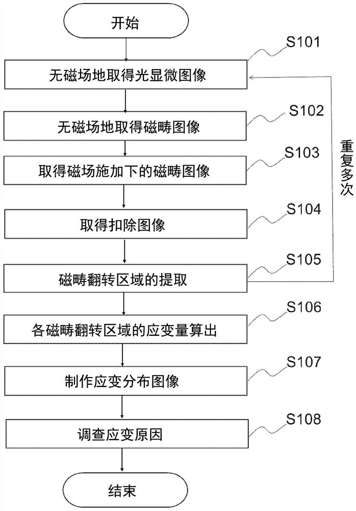
[0093] and figure 2 The difference between the image acquisition method of the illustrated embodiment 1 is that the figure 2 Replace the S102 with S802 at this point. That is, in figure 2 In S102, the magnetic domain image used as a reference is obtained under no magnetic field without applying an external magnetic field. In contrast, in Figure 8 In S802, an external magnetic field is applied to obtain a reference magnetic domain image. Other steps (S101, S103, S104, S105, S106, S107) and figure 2 The image acquisition method in the first embodiment shown is the same, and therefore its description is omitted.
[0094] In the image acquisition method of embodiment 2, as Figure 8 As shown, in the acquisition of a standard magnetic domain image, a magnetic domain image is acquired in a certain desired magnetic field application state. For example, it is also effectiv...
Embodiment 3
[0096] refer to Figure 9 The image acquisition method of the third embodiment will be described.
[0097] In Example 3, until halfway through with Figure 8 The grain boundary image was obtained in the same process as in Example 2 shown. That is, an image of a magnetic domain is acquired, and an image subtracted from an image applied with a predetermined external magnetic field is acquired to acquire an image of a grain boundary region.
[0098] First, the sample 3 is fixed on the sample holder 1, and the surface shape of the sample 3 mounted on the sample holder 1 is observed to obtain a shape image (S901). In addition, no magnetic field is applied from the outside at this point of time. That is, an optical microscopic image is obtained without a magnetic field.
[0099] Next, in the same field of view, a magnetic domain image is acquired with a reference external magnetic field ( S902 ).
[0100] Next, a magnetic domain image is obtained in a state where an external ma...
PUM
 Abstract
Description
Claims
Application Information
 - R&D
- Intellectual Property
- Life Sciences
- Materials
- Tech Scout
- Unparalleled Data Quality
- Higher Quality Content
- 60% Fewer Hallucinations
Browse by: Latest US Patents, China's latest patents, Technical Efficacy Thesaurus, Application Domain, Technology Topic, Popular Technical Reports.
© 2025 PatSnap. All rights reserved.Legal|Privacy policy|Modern Slavery Act Transparency Statement|Sitemap|About US| Contact US: help@patsnap.com


