Millimeter wave low-profile broadband circularly-polarized slot-fed dipole array antenna

A dipole antenna and circularly polarized antenna technology, applied in the field of antennas, can solve the problem of no millimeter wave low-profile broadband circularly polarized slot-fed dipole array antenna, etc., to reduce the profile, expand the axial ratio bandwidth, optimize the bevel effect

Inactive Publication Date: 2021-06-25
ANHUI UNIVERSITY
View PDF14 Cites 12 Cited by
  • Summary
  • Abstract
  • Description
  • Claims
  • Application Information

AI Technical Summary

Problems solved by technology

There have been a lot of work reports on low-profile antennas and various millimeter-wave circularly polarized anten...

Method used


Image

  • Millimeter wave low-profile broadband circularly-polarized slot-fed dipole array antenna
  • Millimeter wave low-profile broadband circularly-polarized slot-fed dipole array antenna
  • Millimeter wave low-profile broadband circularly-polarized slot-fed dipole array antenna

Examples


Embodiment 1

[0063] For millimeter wave circularly polarized antennas, this embodiment designs a millimeter wave low-profile broadband circularly polarized slot-fed dipole array antenna, which can be used in millimeter wave wireless communication systems. The impedance bandwidth of the antenna covers the 27.59GHz-34.68GHz frequency band, and the axial ratio bandwidth covers the 25.9GHz-35.37GHz frequency band. The design can also be optimized to cover the specified frequency band. The antenna mainly includes an antenna radiator, a parasitic patch, a broadband SIW sequential rotating feed network, a three-layer dielectric substrate, and metallized through holes.

[0064] The antenna radiator is a dipole patch located on the upper surface of the top dielectric substrate, surrounded by chamfered parasitic patches. Metallized through-holes are placed on the periphery of the radiator on the top layer to form a cavity and improve the gain characteristics of the antenna. The three-layer dielectr...

Embodiment 2

[0068] The invention designs a millimeter-wave low-profile broadband circular polarization slot-fed dipole array antenna, which can be used in a millimeter-wave wireless communication system. The volume of the antenna is only 23mm×23mm×1.829mm, the impedance bandwidth can cover the 27.59GHz-34.68GHz frequency band, the axial ratio bandwidth covers the 25.9GHz-35.37GHz frequency band, and it has a stable radiation pattern, high gain, and stable gain.

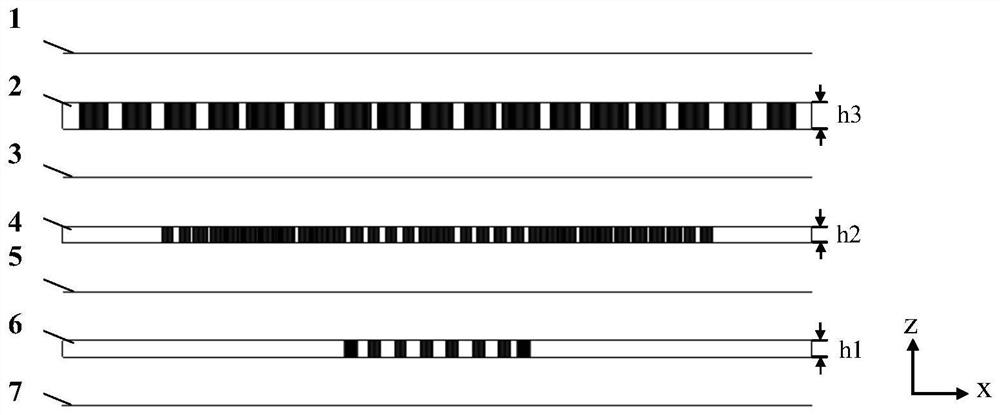
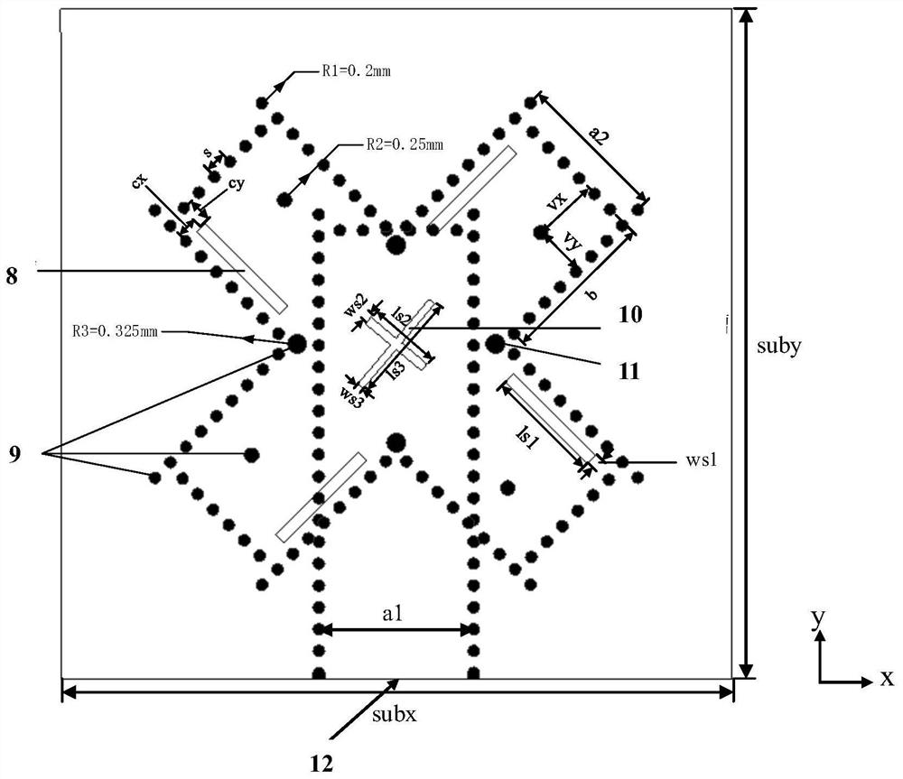
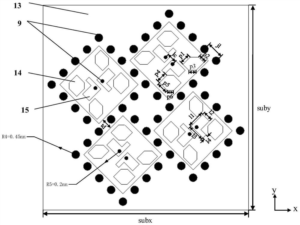
[0069] Such as figure 1 , figure 2 and image 3 Shown is a schematic diagram of the physical structure of the millimeter-wave low-profile broadband circularly polarized slot-fed dipole array antenna. The area dimensions of the millimeter-wave low-profile broadband circularly polarized slot-fed dipole antenna array are width subx=23mm; length suby=23mm; the thicknesses of the three-layer dielectric substrate are: bottom layer h1=0.508mm, middle layer h2 =0.508mm, the top layer h3=0.813mm. The dielectric substrate is rectangul...


PUM

PropertyMeasurementUnit
Widthaaaaaaaaaa
Lengthaaaaaaaaaa
Heightaaaaaaaaaa

Abstract

The invention provides a millimeter-wave low-profile broadband circularly-polarized slot-fed dipole antenna array. The millimeter-wave low-profile broadband circularly-polarized slot-fed dipole antenna array comprises an antenna radiator, parasitic patches, a broadband SIW sequential rotating feed network, a three-layer dielectric substrate and metalized through holes, wherein the radiator is arranged on the upper surface of the top dielectric substrate, and the parasitic patches are arranged around the radiator; the broadband SIW sequential rotation feed network is arranged on the bottom layer and the middle layer of the antenna; and the metalized through holes are positioned at the peripheries of the top-layer radiator and the parasitic patches. On the basis of a common circularly-polarized magnetoelectric dipole antenna structure, the chamfered parasitic patches are introduced to the periphery of the dipole antenna, so the structure realizes the characteristic of broadband circular polarization while having a low profile. Meanwhile, sequential rotation feed is utilized at the lower layer of a unit, so the axial ratio bandwidth of the antenna array is expanded. The antenna is small in physical size, low in profile and suitable for 5G millimeter wave circular polarization communication.

Description

technical field [0001] The invention relates to the technical field of antennas, in particular to a millimeter-wave low-profile broadband circularly polarized slot-fed dipole array antenna. Background technique [0002] With the rapid development of wireless communication technology, the millimeter wave band has attracted more and more attention and research due to its rich spectrum resources. Circular polarization can suppress multi-path fading and is not affected by the Faraday rotation effect in the ionosphere, so it is widely used in satellite communications and other occasions. Furthermore, as an important front-end device in a wireless communication system, the circularly polarized antenna has been widely studied, and is also developing in the direction of miniaturization, low profile, high gain, and wide bandwidth. In the millimeter wave band, in order to compensate for the propagation loss of electromagnetic waves in the air, the antenna needs to have high gain char...

Claims


Application Information

Patent Timeline
IPC IPC(8): H01Q21/24H01Q1/50H01Q9/04
CPCH01Q21/24H01Q1/50H01Q9/0407
Inventor 徐光辉朱传明黄道胜杨利霞黄志祥
Owner ANHUI UNIVERSITY
Why Eureka
Try Eureka