
Clock signal generation device and clock signal generation method

A clock signal and generation device technology, applied in the direction of electrical components, automatic power control, etc., can solve the problems of low frequency adjustment accuracy of clock signal, large error of relaxation oscillator, etc.

Pending Publication Date: 2021-06-25
宏晶微电子科技股份有限公司
View PDF0 Cites 0 Cited by
  • Summary
  • Abstract
  • Description
  • Claims
  • Application Information

AI Technical Summary

Problems solved by technology

However, the relaxation oscillator has a large error when adjusting the frequency of the clock signal, and the frequency adjustment accuracy of the clock signal is low

Method used


Image

  • Clock signal generation device and clock signal generation method
  • Clock signal generation device and clock signal generation method
  • Clock signal generation device and clock signal generation method

Examples


Embodiment Construction

[0034] Example embodiments will be described more fully hereinafter with reference to the accompanying drawings, but may be embodied in different forms and should not be construed as limited to the embodiments set forth herein. Rather, these embodiments are provided so that this disclosure will be thorough and complete, and will fully convey the scope of the disclosure to those skilled in the art.

[0035] As used herein, the term "and / or" includes any and all combinations of one or more of the associated listed items.

[0036] The terminology used herein is for describing particular embodiments only and is not intended to limit the present disclosure. As used herein, the singular forms "a" and "the" are intended to include the plural forms as well, unless the context clearly dictates otherwise. It will also be understood that when the terms "comprising" and / or "consisting of" are used in this specification, the stated features, integers, steps, operations, elements and / or co...


PUM


Abstract

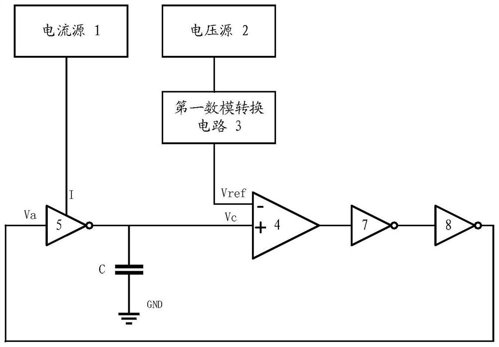
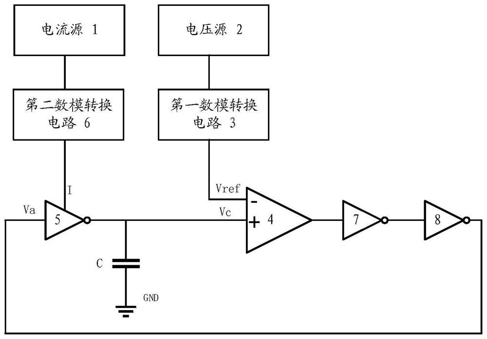
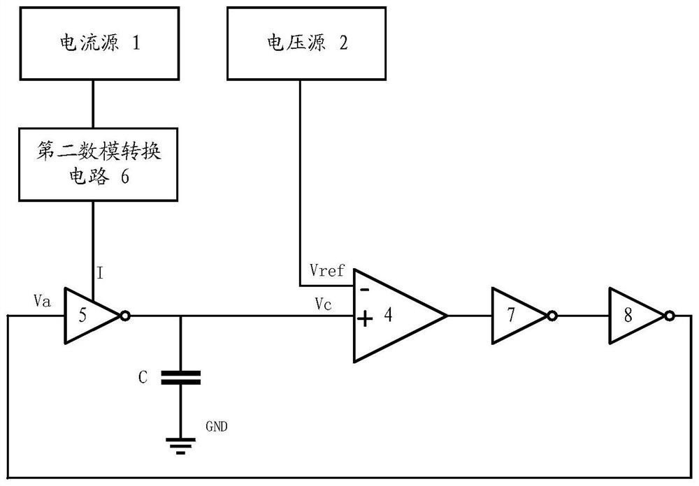
The invention provides a clock signal generation device and a clock signal generation method; the device comprises a voltage source, a current source, a first digital-to-analog conversion circuit, a comparator, a first phase inverter and a capacitor, and the input end of the first digital-to-analog conversion circuit is connected with the output end of the voltage source; the output end of the first digital-to-analog conversion circuit is connected with the first input end of the comparator, and the first digital-to-analog conversion circuit is used for adjusting the voltage output by the voltage source to obtain comparison voltage; the power supply end of the first phase inverter is connected with the output end of the current source, the input end of the first phase inverter is connected with the output end of the comparator, the output end of the first phase inverter is connected with the capacitor and the second input end of the comparator, and current generated by the current source charges the capacitor; and the comparator is used for generating a clock signal according to the comparison voltage and the output voltage of the first inverter. The charging time of the capacitor can be accurately controlled, so that the frequency of the clock signal is accurately controlled, and the frequency adjustment error of the clock signal can be reduced.

Description

technical field [0001] The present disclosure relates to the technical field of electronic circuits, and in particular to a clock signal generating device and a clock signal generating method. Background technique [0002] In order to reduce system cost, most electronic equipment adopts a clock signal generation scheme without crystal oscillator, that is, the oscillator in the chip is used to provide a working clock signal for the chip. [0003] At present, there are mainly the following types of clock signal generation schemes without crystal oscillator: [0004] 1. LC oscillator: The LC oscillator has the advantages of high quality factor, good frequency selection characteristics, and low output clock jitter, but the LC oscillator requires an inductor, which will greatly increase the chip area, and at the same time, due to the high output frequency, the power consumption will also increase. A substantial increase. [0005] 2. Relaxation oscillator: The relaxation oscilla...

Claims


Application Information

Patent Timeline
Patent Type & Authority Applications(China)
IPC IPC(8): H03L7/16H03L7/099
CPCH03L7/16H03L7/099
Inventor 陈晓飞刘伟
Owner 宏晶微电子科技股份有限公司
Learn More