Circuit board structure
A circuit board and backplane technology, which is applied in the structural connection of printed circuits, printed circuits, printed circuit components, etc., can solve the problems of inflexible configuration and production, and rigid design of circuit board products, so as to reduce hardware design costs and enhance general use. The effect of flexibility and flexible configuration
- Summary
- Abstract
- Description
- Claims
- Application Information
AI Technical Summary
Problems solved by technology
Method used
Image

Examples
Embodiment 1
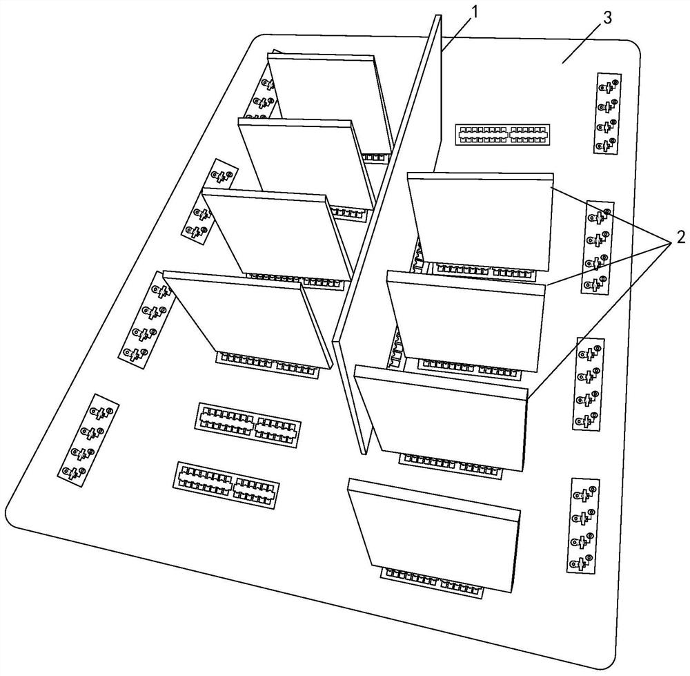
[0101] See figure 1 , figure 1 A schematic diagram showing the circuit board structure of Embodiment 1 of the present invention. The details are as follows:
[0102] Board construction, including:
[0103] At least one base module 3 and at least one core control module 1 and at least one functional module 2 assembled on the base module 3, and any function module 2 and any core control module 1 are electrically connected to the base module 3; wherein, the base module 3. The core control module 1 and the functional module 2 are both of sheet laminate structure.
[0104] It should be noted that the backplane module 3, the core control module 1, and the functional module 2 are all chip laminate structures, which include but are not limited to single-layer boards (one-sided copper clad), double-layer boards (double-sided Copper clad) and multi-layer board structure are all within the scope of this application, and can be selected according to the hardware design requirements of...
Embodiment 2
[0111] Further improvements are made based on the versatile circuit board structure of Embodiment 1:
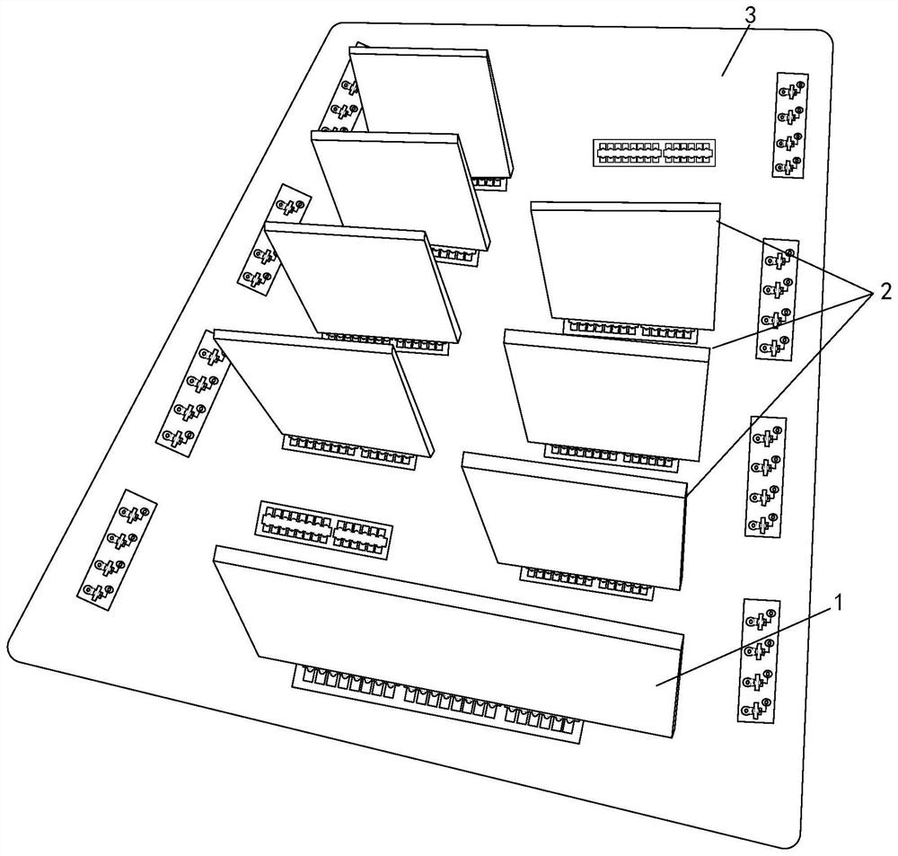
[0112] combine figure 1 with figure 2 As shown, the positional relationship between the core control module 1, the functional module 2 and the base module 3 can be vertical, or can form a certain inclination angle according to actual design requirements.
[0113]The number of functional modules 2 is generally configured in multiples to adapt to the ever-changing needs of customers. Among them, two adjacent functional modules 2 are parallel to each other, perpendicular to each other, or at a certain inclination angle, and the core The control module 1 and the functional module 2 are parallel to each other, can also be perpendicular to each other, and can also be at a certain angle of inclination. Those skilled in the art can determine the three types of modules according to the size of the base module 3 and the design requirements of the circuit board product. Flexible desi...
Embodiment 3
[0125] Compared with assembly processes such as pin headers and sockets, in the third embodiment, the circuit board of the core control module 1 is directly welded to the common base plate, eliminating the need for intermediate parts such as pin headers and sockets, thereby greatly reducing the cost of materials. In the third embodiment, the welding process is used to realize the assembly between the core control module 1 and the bottom plate module 3, as follows:
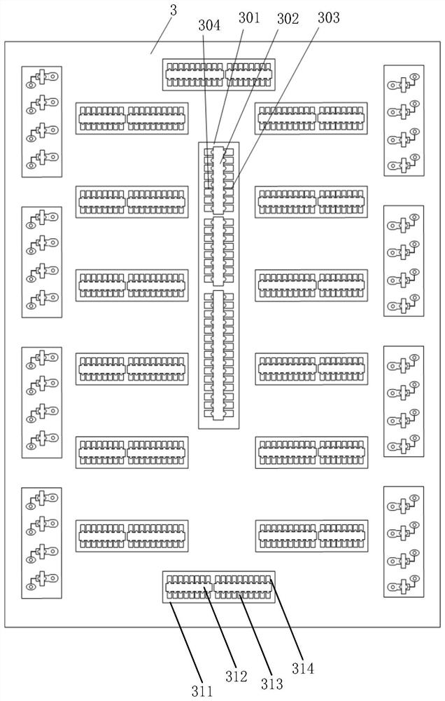
[0126] See Figure 3 to Figure 6 , image 3 shows a schematic plan view of a backplane module, Figure 4 show image 3 A schematic plan view of the interface area 301 of the central core control module, Figure 5 , 6 A schematic structural view of the core control module 1 is shown respectively. The core control module 1 has several core board tongue plates 101; the two sides of any core board tongue plate 101 are provided with mutually symmetrical core board front row type solder tabs 102 and core board rever...
PUM
 Abstract
Description
Claims
Application Information
 - R&D
- Intellectual Property
- Life Sciences
- Materials
- Tech Scout
- Unparalleled Data Quality
- Higher Quality Content
- 60% Fewer Hallucinations
Browse by: Latest US Patents, China's latest patents, Technical Efficacy Thesaurus, Application Domain, Technology Topic, Popular Technical Reports.
© 2025 PatSnap. All rights reserved.Legal|Privacy policy|Modern Slavery Act Transparency Statement|Sitemap|About US| Contact US: help@patsnap.com