Supercharge Your Innovation With Domain-Expert AI Agents!

Real-time elimination method for melting near-surface layer forming defects of laser powder bed

A laser powder and laser remelting technology, which is applied in the field of additive manufacturing, can solve the problems of increasing forming time and cost, and cannot completely eliminate forming defects, and achieve the effects of timely elimination of pore defects, sufficient response time, and reduced surface roughness

Active Publication Date: 2021-06-29
NANJING UNIV OF SCI & TECH
View PDF7 Cites 0 Cited by
  • Summary
  • Abstract
  • Description
  • Claims
  • Application Information

AI Technical Summary

Problems solved by technology

However, in some special cases, post-processing not only cannot completely eliminate forming defects, but also adds additional forming time and cost

Method used


Image

  • Real-time elimination method for melting near-surface layer forming defects of laser powder bed
  • Real-time elimination method for melting near-surface layer forming defects of laser powder bed
  • Real-time elimination method for melting near-surface layer forming defects of laser powder bed

Examples


Embodiment 1

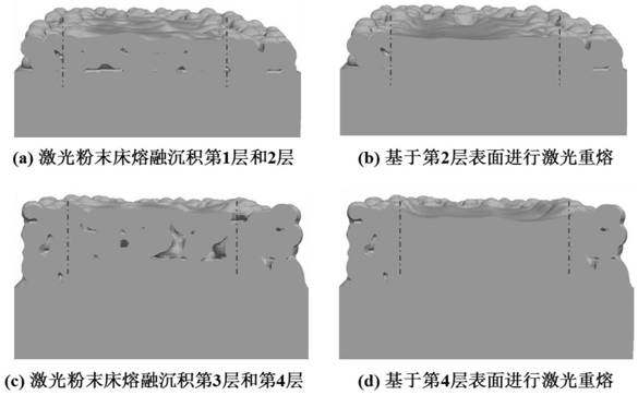
[0053] This embodiment provides a laser powder bed melt proximal surface forming defect real-time elimination method, and the specific implementation steps are as follows:

[0054] Step 1: Monitor the distance H of the laser powder melt forming defect and the surface of the deposited layer by the external acquisition system.

[0055] Step 2: Determine the location of the defect in accordance with the distance h of the surface of the forming defect and the deposition layer, the specific steps are as follows:

[0056] 1) When the H> N deposition layer thickness, the laser remelling is immediately performed, and the reduction of deposited layer defects after the remelting is determined. If the defect eliminates the requirements, the release, the laser powder is melted; in turn, optimization The remelting process remelted again until the defect elimination meets the requirements;

[0057] 2) When the H ≤ N is deposited, the powder is performed, and the laser powder is melted;

[0058]...

Embodiment 2

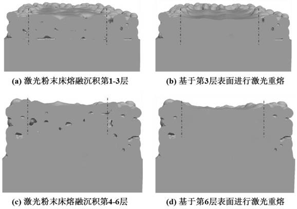
[0067] This embodiment provides a laser powder bed melt proximal surface forming defect real-time elimination method, and the specific implementation steps are as follows:

[0068] Step 1: Monitor the distance H of the laser powder melt forming defect and the surface of the deposited layer by the external acquisition system.

[0069] Step 2: Determine the location of the defect in accordance with the distance h of the surface of the forming defect and the deposition layer, the specific steps are as follows:

[0070] 1) When the H> N deposition layer thickness, the laser remelling is immediately performed, and the reduction of deposited layer defects after the remelting is determined. If the defect eliminates the requirements, the release, the laser powder is melted; in turn, optimization The remelting process remelted again until the defect elimination meets the requirements;

[0071] 2) When the H ≤ N is deposited, the powder is performed, and the laser powder is melted;

[0072]...


PUM

PropertyMeasurementUnit
Thicknessaaaaaaaaaa
Depthaaaaaaaaaa
Particle sizeaaaaaaaaaa

Abstract

The invention provides a real-time elimination method for melting near-surface-layer forming defects of a laser powder bed. The method comprises the steps that firstly, the distance h between the melting forming defects of the laser powder bed and the surface of deposition layers is monitored in real time through an external collection system; then the position of the defects is judged, when h is greater than the thickness of N deposition layers, laser remelting is carried out immediately; and when h is smaller than or equal to the thickness of the N deposition layers, powder laying and laser powder bed fusion forming are carried out, and the steps are repeated till the accumulated printing height H reaches the designated height, and laser remelting is carried out on the surfaces of the deposition layers. Compared with an existing forming technology, the method has the advantages that the surface roughness of a formed part can be reduced, the pore defects can be eliminated in time, compared with a forming mode that laser remelting is conducted after layer-by-layer remelting and continuous multi-layer deposition are conducted, the forming efficiency is greatly improved, and meanwhile more sufficient response time is gained for defect online feedback adjustment.

Description

Technical field: [0001] The present invention belongs to the technical field of additive manufacturing, and more particularly to a laser powder bed molten proximal surface forming defect real time elimination method. Background technique: [0002] Adapter manufacturing is an advanced rapid forming technique that achieves near net mold shape of complex parts by computer assistance techniques. Compared with traditional manufacturing techniques, the additive manufacturing technology effectively improves the forming efficiency and material utilization, which is expected to be freely manufactured. Laser Powder Bed Fusion (LPBF) is a typical metal 3D printing technology that directly melts the metal powder directly, and the forming member has excellent mechanical properties and dimensional accuracy. However, the molten forming process of the laser powder is extremely complex and the condition is extremely complicated, and it is easy to form a splash, pore, crack, etc., which seriously ...

Claims


Application Information

Patent Timeline
IPC IPC(8): B22F10/28B22F10/85B22F10/364B33Y10/00B33Y50/02B33Y40/20
CPCB22F3/24B33Y30/00B33Y50/02B33Y40/20Y02P10/25
Inventor 刘婷婷张玲廖文和韦辉亮曹洋
Owner NANJING UNIV OF SCI & TECH
Features
  • R&D
  • Intellectual Property
  • Life Sciences
  • Materials
  • Tech Scout
  • Unparalleled Data Quality
  • Higher Quality Content
  • 60% Fewer Hallucinations
Learn More