Tensile high-strength hook forge piece forging device

A high-strength, hook-head technology, used in forging/pressing/hammer devices, forging presses, forging presses, etc., can solve the problem of reducing the service life of the hook, increasing the shear force between the hook head and the structure, manual overturning and positioning uncontrollable progress, etc.

Active Publication Date: 2021-07-06
CHONGQING JINKAI SPECIAL STEEL PROD
View PDF5 Cites 0 Cited by
  • Summary
  • Abstract
  • Description
  • Claims
  • Application Information

AI Technical Summary

Problems solved by technology

[0004] At present, in the forging process of the hook, the hook body is forged in advance, and then the hook head is forged and formed using a forging die. The forging molding of the hook head, because the hook head is the connection between the hook and the lifting equipment, the progress of manual turning and positioning is uncontrollable, and it is easy to cause eccentricity between the hook head and the structure, which makes the hook increase in subsequent use. The shear force between the hook head and the structure reduces the service life of the hook

Method used


Image

  • Tensile high-strength hook forge piece forging device
  • Tensile high-strength hook forge piece forging device
  • Tensile high-strength hook forge piece forging device

Examples


Embodiment 1

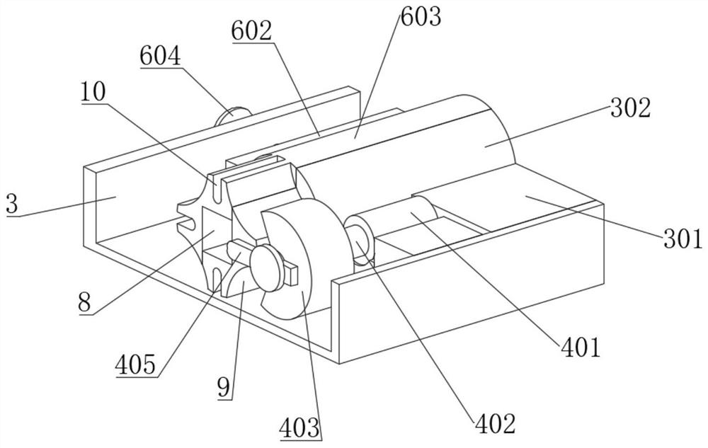
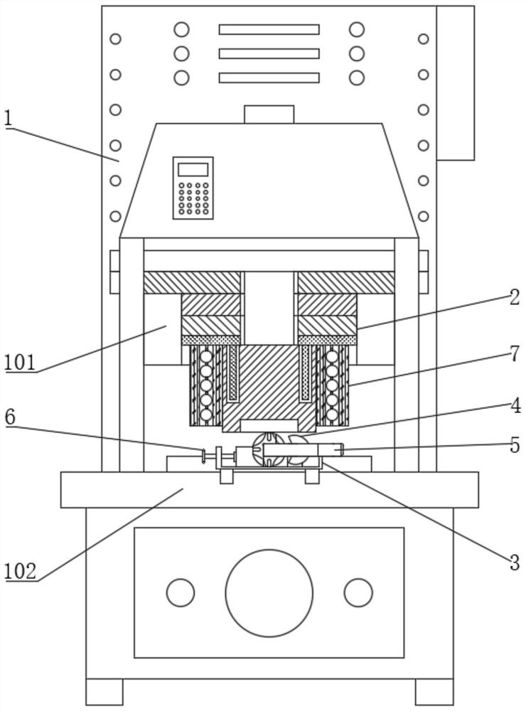
[0058] see Figure 1-13 , a high-strength tensile hook forging forging device, including a forging body 1, the upper end of the forging body 1 is fixedly connected with a mold mounting frame 101, and the upper end of the forging body 1 is fixedly connected with a forging frame located at the lower side of the mold mounting frame 101. Workbench 102, the forging mold 2 is installed in the mold mounting frame 101, the front end of the forging workbench 102 is fixedly installed with the forging holder 3 matching the forging mold 2, and the upper end of the forging holder 3 is fixedly connected with a fixed Arc block 301, the upper end of the forging clamp seat 3 is connected with the flip assembly 4 located at the front side of the fixed arc block 301, the upper end of the forged clamp seat 3 is connected with the clamping assembly 6 located on the left side of the fixed arc block 301, the clamp A hook 5 is installed between the holding assembly 6 and the fixed arc block 301; plea...

Embodiment 2

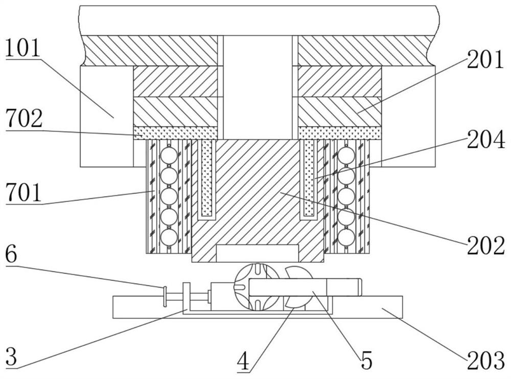
[0066] see Figure 1-13 , where the same or corresponding components as those in Embodiment 1 use the corresponding reference numerals as in Embodiment 1, and for the sake of simplicity, only the differences from Embodiment 1 will be described below. The difference between this embodiment 2 and embodiment 1 is: please refer to figure 2 and image 3 , the lower end of the mold mounting frame 101 is fixedly installed with a heating assembly 7, and the heating assembly 7 includes a heating sheath 701, and the left and right inner walls of the mold mounting frame 101 are fixedly connected with a heating sheath 701, and the forging punch 202 is located between the two heating jackets 701 and matches with the heating jackets 701 . The heating sheath 701 heats up the forging punch 202, reduces the generation of oxide skin on the end surface of the hook 5 caused by the temperature difference of the forging punch 202, improves the forging quality of the hook 5, homogenizes the cryst...

Embodiment 3

[0071] see Figure 1-13 , wherein the same or corresponding components as those in Embodiment 1 use the corresponding reference numerals as in Embodiment 1, and for the sake of simplicity, only the differences from Embodiment 1 are described below. The difference between this embodiment 3 and embodiment 1 is: please refer to Figure 13 , a method for using a tensile high-strength hook head forging device, comprising the following steps:

[0072] S1. Place the formed hook 5 on the upper end of the forged holder 3;

[0073] S2. Turn the locking threaded rod 601 to drive the locking slider 602 and the clamping left rod 603 to move to the fixed arc block 301, and clamp and fix the hook 5;

[0074] S3. The forging body 1 drives the forging die 2 to act on the hook 5 to forge the hook head of the hook 5;

[0075] S4. After forging once, start the turning component 4, and drive the hook 5 to turn over on the forging holder 3;

[0076] S5. Repeat steps S3-S4;

[0077] S6. After t...


PUM


Abstract

The invention discloses a tensile high-strength hook forge piece forging device, and belongs to the field of forging. The tensile high-strength hook forge piece forging device comprises a forging machine body, the upper end of the forging machine body is fixedly connected with a die mounting frame, and the upper end of the forging machine body is fixedly connected with a forging workbench located on the lower side of the die mounting frame. A forging die is installed in the die mounting frame, a forging clamping base matched with the forging die is fixedly installed at the front end of the forging workbench, and a fixed arc block is fixedly connected to the upper end of the forging clamping base. The forging clamping base and a clamping assembly can be matched with each other to clamp and position a lifting hook, and the positioning precision of the lifting hook in the forging process is effectively improved; and a turnover assembly drives the lifting hook to turn over and rotate, the position precision of the lifting hook in the forging process is effectively improved, the concentricity of a hook head and a structure part is effectively improved, the shearing force generated when the lifting hook is used is reduced, the tensile strength of the lifting hook is improved, and the service life of the lifting hook is effectively prolonged.

Description

technical field [0001] The invention relates to the field of forging, and more specifically, relates to a forging device for a high-strength hook forging with high tensile strength. Background technique [0002] Forging is a processing method that uses forging machinery to apply pressure to metal blanks to cause plastic deformation to obtain forgings with certain mechanical properties, certain shapes and sizes. It is one of the two major components of forging (forging and stamping). Forging can eliminate defects such as as-cast porosity produced in the metal smelting process and optimize the microstructure. At the same time, due to the preservation of complete metal flow lines, the mechanical properties of forgings are generally better than castings of the same material. For important parts with high loads and severe working conditions in related machinery, forgings are mostly used, except for plates, profiles or weldments that can be rolled with simpler shapes. [0003] Th...

Claims


Application Information

Patent Timeline
Patent Type & Authority Applications(China)
IPC IPC(8): B21K1/72B21J9/00B21J13/12B21J13/02
CPCB21K1/72B21J9/00B21J13/12B21J13/02
Inventor 黄小六
Owner CHONGQING JINKAI SPECIAL STEEL PROD
Why Eureka
Try Eureka