Air inlet prevention material conveying device and air inlet prevention method of material conveying device
A technology of material transmission and material import, which is applied in the anti-intake material transmission device and the field of anti-intake, can solve the problems of paralysis and blockage of the discharge system, and achieve the effect of cooling
- Summary
- Abstract
- Description
- Claims
- Application Information
AI Technical Summary
Problems solved by technology
Method used
Image
Examples
Embodiment 1
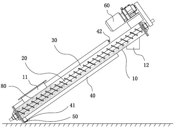
[0027] Such as figure 1 As shown, the air supply gas material transmission device according to the present invention is a conveying tank 10 made of seamless steel tube, and the conveying tank 10 has material inlet 11 and material outlet 12, and the material inlet 11 is disposed upward. The air solution of the pyrolyzed carbonization furnace is connected, and the material outlet 12 is disposed toward the discharge. The conveying tank 10 is tilted, and the inclination angle is 10-30 °. The low position of the delivery tank 10 is provided with an artificial discharge port 50 to facilitate manually derive the material 80 of the delivery tank 10 to the delivery tank 10. The conveying tank 10 has a spiral conveying shaft 20, and the spiral conveying shaft 20 is a shaft spiral, which is suitable for transporting non-stick dry powder materials and small particulate materials. The spiral conveying shaft 20 is disposed with the conveying tank 10, and the inclination angle is consistent with...
Embodiment 2
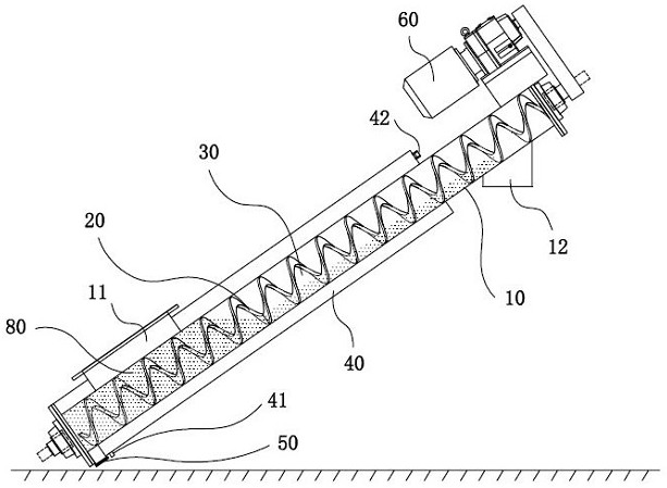
[0032] Such as figure 2 As shown, in Example 2 and Example 1 showed that the screw conveying shaft 20 is a shaft helix. The gap between the inner wall of the conveying tank 10 and the outer diameter of the shaft helical blade is smaller, and the gap is not sufficient to form a material to return the passage 30. In this embodiment, the material retardation passage 30 is formed in the middle of the shaft spiral. Under the premise of the inclinement setting of the conveying tank 10 and the helical conveying shaft 20, the material 80 falls along the intermediate air column of the shaft spiral to the material inlet 11.
Embodiment 3
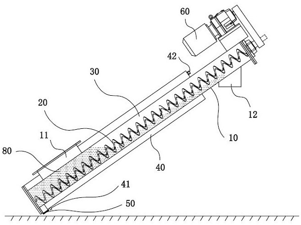
[0034] Such as image 3 As shown, in Example 3 and Example 2 differed between the intermediate air of the inner wall of the tank body and the unscrupulous spiral blade, the gap and the intermediate air column of the shaft spiral It can be a material drop channel 30. The distal end of the shaft spiral is sag, and the material 80 can be accumulated above the distal end of the shaft screw, and the upper portion of the spiral conveying shaft 20 can be reduced without material 80 coverage.
PUM
 Abstract
Description
Claims
Application Information
 - R&D
- Intellectual Property
- Life Sciences
- Materials
- Tech Scout
- Unparalleled Data Quality
- Higher Quality Content
- 60% Fewer Hallucinations
Browse by: Latest US Patents, China's latest patents, Technical Efficacy Thesaurus, Application Domain, Technology Topic, Popular Technical Reports.
© 2025 PatSnap. All rights reserved.Legal|Privacy policy|Modern Slavery Act Transparency Statement|Sitemap|About US| Contact US: help@patsnap.com


