Reflector surface sum-difference network antenna

A reflective surface and antenna technology, applied in the directions of antennas, waveguide horns, electrical components, etc., can solve the problems of unfavorable performance requirements such as high resolution of the antenna, the overall size of the antenna increases, and the level of the main lobe of the difference beam is reduced.

Active Publication Date: 2021-07-06
NANJING UNIV
View PDF9 Cites 1 Cited by
  • Summary
  • Abstract
  • Description
  • Claims
  • Application Information

AI Technical Summary

Problems solved by technology

However, for the positive-fed reflector antenna, the feed horn needs to be installed on the focal point of the paraboloid, which will inevitably block the center of the paraboloid's mouth surface field, reducing the energy of the main lobe of the pattern and causing multiple reflections. Affects the electric field distribution of the surface field at the antenna port, eventually leading to a decrease in the main lobe level of the sum and difference beam, an increase in the side lobe level, and a decrease in antenna gain. In severe cases, the main lobe of the pattern will be deformed
In order to overcome the shortcoming of the feed source shielding of the feedforward antenna, the method of offset feeding can also be used (Offset-parabolic-reflector antennas: A review [J]. Proceedings of the IEEE, 1978, vol.66, no.12, pp.1592-1618), but the offset-fed antenna is not conducive to forming a sum-difference beam with a good shape
This is because the equivalent phase center of the feed source will largely deviate from the focus of the reflector antenna during offset feeding. As the distance between the phase center and the focus of the paraboloid increases, the problem of offset will be serious. On the one hand, it will affect The performance of the sum and difference beam makes the side lobe increase, the beam deformation and the null depth become larger, which is extremely unfavorable for meeting the performance requirements such as high resolution of the antenna; on the other hand, the offset feed makes the design of the antenna structure more difficult. In addition, it is necessary to carry out complex shaping of the horn feed, which eventually leads to an increase in the overall size of the antenna, which makes it difficult to guarantee the fixed installation and service life of the antenna

Method used


Image

  • Reflector surface sum-difference network antenna
  • Reflector surface sum-difference network antenna
  • Reflector surface sum-difference network antenna

Examples


Embodiment 1

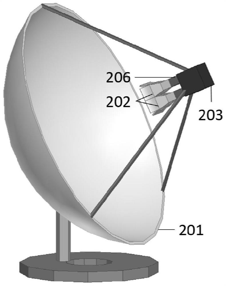
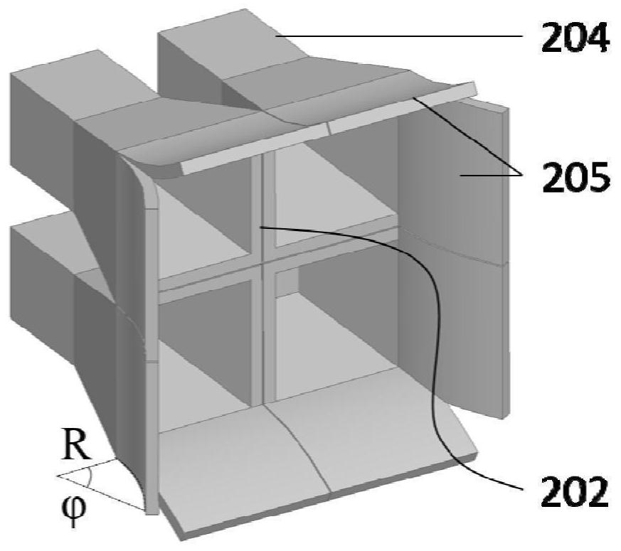
[0027] refer to figure 2 , image 3 , this example is designed as a reflector antenna with a 2×2 array feed, and the design steps are as follows: The 2×2 array reflector antenna of this example includes a reflector antenna 201, a pair of monaural horn feeds 202, and the sum and difference network203. In this antenna, the reflector antenna 201, the sum and difference network 203, and the standard waveguide are common structures. The monaural horn feed 202 is expanded from the standard waveguide structure 204 into a horn antenna, and the monaural structure 205 is extended from both sides thereof. It should be noted that in this example, because the feed array is a 2×2 structure, each feed speaker is a monaural horn feed, and all monaural structures are a section of cylindrical surface with a radius of R , the angle is All monaural structures together wrap the outermost part of the entire array. If the feed array has more than 2 rows or 2 columns of speaker feeds, you only...

Embodiment 2

[0029] The beam shape designed in this example is a fan beam, the working frequency range is 76-77GHz, the working mode is horizontal scanning, and the structure uses a box-type reflector antenna.

[0030] The present invention belongs to the feedforward parabolic reflector antenna, and the design steps are as follows: Figure 4 As shown, the sector and difference beam horizontal scanning box antenna consists of a reflector antenna 301, a pair of metal plates 302, a pair of transition structures 304, a pair of monaural horn feeds 303, a curved waveguide 305 and a sum and difference network 306 . Firstly, determine the shape size of the parabolic reflector. According to the central operating frequency of 76.5GHz, the corresponding operating wavelength λ is calculated to be about 3.92mm, and then the aperture D of the rectangular mouth surface field of the parabolic reflector (D E and D H ) are obtained by estimating the target azimuth angle and elevation angle of the beam an...


PUM


Abstract

The invention provides a reflector sum-difference network antenna. The antenna comprises a reflector antenna, a feed source and a sum-difference network; the feed source is connected to the sum-difference network, the feed source adopts a monaural horn, and more than two monaural horns are symmetrically distributed on two sides of a focus of the reflector antenna in pairs; the single-ear horn is in the shape of a pyramid horn, and the edge of the horn mouth extends to form a single-ear structure. According to the novel reflector sum-difference network antenna provided by the invention, an effective solution is provided for the shielding problem of a feed source to a reflector antenna, and fan-shaped sum-difference beams which are high in gain, low in side lobe, low in zero value depth and highly symmetrical can be obtained while the offset of the feed source phase center relative to the focus of the reflector is reduced.

Description

technical field [0001] The invention relates to the field of radio frequency antennas, in particular to a sum and difference network antenna structure using a monaural horn as a feed source. Background technique [0002] In recent years, millimeter-wave radar technology has become increasingly mature. Compared with infrared, millimeter-wave has less atmospheric attenuation, better penetration of smoke and dust, and less affected by weather. These excellent performances determine that millimeter-wave radar has all-weather With all-weather working ability, it has a wide range of engineering applications in traffic supervision, security deployment and control, and target search. As an important part of the millimeter-wave radar, the performance of the antenna directly affects the detection and tracking capabilities of the radar. [0003] Many researches have been done on millimeter-wave radar antennas at home and abroad, such as offset reflector antennas, multi-beam antennas, ...

Claims


Application Information

Patent Timeline
Patent Type & Authority Applications(China)
IPC IPC(8): H01Q13/02H01Q15/16
CPCH01Q13/02H01Q15/16
Inventor 纪小丽王珂廖轶明
Owner NANJING UNIV
Why Eureka
Try Eureka