Inverter output relay pull-in impact current suppression method and device

A technology for outputting relays and inrush currents, applied in the direction of output power conversion devices, electrical components, etc., can solve problems such as increased equipment costs, incomplete suppression, and limited scope of application, so as to improve applicability and eliminate the impact of relay pull-in The effect of current

Active Publication Date: 2021-07-06
JIANGSU GOODWE POWER SUPPLY TECHNOLOGY CO LTD +1
View PDF6 Cites 0 Cited by
  • Summary
  • Abstract
  • Description
  • Claims
  • Application Information

AI Technical Summary

Problems solved by technology
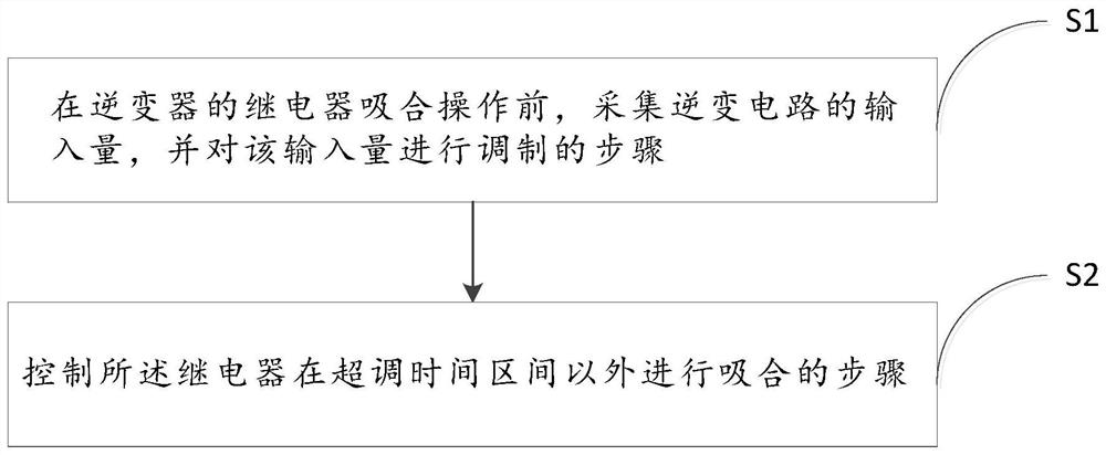
However, the suppression method described in this prior art still cannot completely solve the problem of inrush current generated by the inverter output relay, and it still has the following technical defects:
[0006] 1) It is necessary to collect the AC port-to-ground voltage and the inverter-to-ground common-mode voltage at the same time, and to calculate the collected limited voltage. The suppression method itself is complicated and difficult to implement;
[0007] 2) While requiring the inverter to output complete AC, it also needs to superimpose DC. Since the input of most inverter applications does not have a boost function, then when 1 / 2 of the bus voltage is very close to the peak value of the mains voltage When it is close, there is almost no space to continue to superimpose the DC component on half of the bus voltage, that is, the suppression method fails;
[0009] 4) Based on defect 3, if the DC component to be compensated is large, the bus voltage needs to be boosted, and the boost of the bus voltage will directly lead to higher requirements for the withstand voltage level of devices such as IGBTs and capacitors on the bus
Taking the aforementioned invention patent application as an example, in order to meet its requirements, the input DC bus voltage is required to reach 933V (220*√2*2+(220*√2*2 / 2)), and the IGBT used under normal conditions The withstand voltage level is only 700V, that is, IGBT and capacitor devices with higher withstand voltage levels will directly increase the cost of equipment;
[0010] 5) Based on defect 3 and defect 4, another problem caused by boosting the bus voltage is the rise of the DC voltage that needs to be compensated, and it is difficult to achieve high-voltage inverter balance on the normal inverter.
[0011] In view of this, the existing technology should be improved to solve the technical problems that the inrush current generated by the pull-in of the inverter output relay is difficult to suppress, the scope of application is limited, and the suppression is not thorough.

Method used


Image

  • Inverter output relay pull-in impact current suppression method and device
  • Inverter output relay pull-in impact current suppression method and device
  • Inverter output relay pull-in impact current suppression method and device

Examples


Embodiment 1

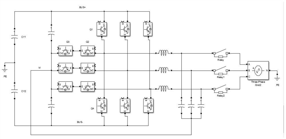
[0034] Let us first talk about the topology structure corresponding to the method for suppressing the inrush current of the inverter output relay in the present invention. figure 1 It is a schematic diagram showing the main circuit structure of a three-phase T-type three-level inverter provided in a preferred embodiment of the present invention. It should be noted that this preferred embodiment of the present invention is only illustrated by taking a three-phase T-type three-level inverter as an example, and the application of the preferred embodiment of the present invention should not be affected by the topology of the inverter. Inverting circuits of different topologies can modulate the corresponding input quantities according to the same principle, so as to achieve the technical purpose of this preferred embodiment of the present invention as well.

[0035] see figure 1 ,according to figure 1 In the direction presented, the main circuit in Embodiment 1 includes a DC side...

Embodiment 2

[0046] Figure 4It is a schematic diagram showing the main circuit structure of the three-phase I-type three-level inverter provided in the second embodiment of the present invention; in the second embodiment of the present invention, the DC / AC converter is also a three-level topology, and The difference from the first embodiment is that the first embodiment is a three-phase T-type three-level inverter, while the second embodiment is a three-phase I-type three-level inverter.

[0047] The second embodiment uses the same method as the first embodiment to define and distinguish the relays (IGBTs) in the circuit, and arrange the switches in the same order as the first embodiment. Therefore, the circuit corresponding to the second embodiment can collect and modulate the input quantity in the same manner as the first embodiment, and the specific process can refer to the same part in the first embodiment, which will not be repeated here.

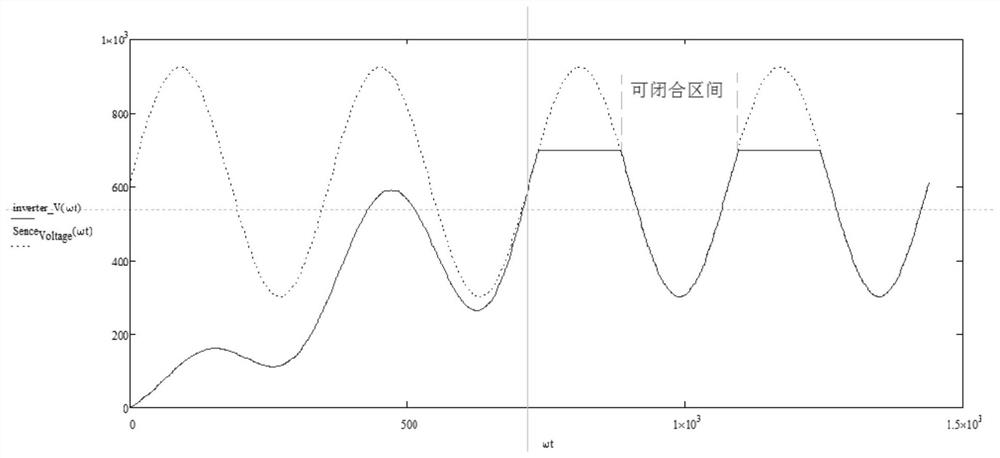
[0048] As for the determination of the ove...

Embodiment 3

[0051] Figure 5 It is a schematic diagram showing the main circuit structure of the two-level three-phase inverter circuit provided in another preferred embodiment of the present invention. see Figure 5 , in the third embodiment, a two-level three-phase inverter circuit is provided, according to Figure 5 In the direction presented, the circuit in Embodiment 3 includes a DC side and an AC side from left to right, and the DC ports on the DC side are respectively connected to the positive pole of the DC bus of the inverter, the midpoint of the DC bus, and the negative pole of the DC bus. On the AC side, one end of the same three AC switches is connected to the AC side of the DC / AC converter through the AC filter, and the other side of the three AC switches is connected to the AC port. As in Embodiment 1, define the left end of the inductance and capacitance as the first segment, and the right end as the second end, see Figure 5 , the first ends of the three inductors are r...


PUM


Abstract

The invention provides an inverter output relay pull-in impact current suppression method and device. The method comprises the following steps: S1, collecting the input quantity of an inverter circuit before the pull-in operation of a relay of an inverter, and modulating the input quantity; and S2, controlling the relay to perform actuation outside the overshoot time interval. According to the invention, the inverter applying the method can effectively reduce and eliminate the impact current generated when the relay of the inverter is actuated, can overcome the technical defects of the existing suppression method under extreme conditions, and improves the applicability of the impact current suppression method.

Description

technical field [0001] The invention relates to the technical field of inverter electric control in the electric power industry, in particular to a method and device for suppressing the inrush current of an inverter output relay. Background technique [0002] In new energy grid-connected power generation systems such as photovoltaic power generation, wind power generation, and energy storage, the inverter performs energy conversion and transmission tasks. The AC filter inside the inverter is connected to the grid through an AC switch such as a relay. The pull-in of the relay can make the inverter connect to the grid, so as to realize the energy transmission with the grid. [0003] In circuit science, when the load is energized, a large current is usually generated, which is the inrush current. Similarly, when the switching power supply in the inverter is started, it is also easy to generate inrush current due to the voltage difference between the two ends of the switch. Th...

Claims


Application Information

Patent Timeline
IPC IPC(8): H02M1/36
CPCH02M1/36
Inventor 何晓东黄敏方刚卢进军黄榜福
Owner JIANGSU GOODWE POWER SUPPLY TECHNOLOGY CO LTD
Why Eureka
Try Eureka