Fixed turnout track and vehicle-mounted track transfer system
A rail vehicle and track technology, applied in the field of fixed turnout track and vehicle-mounted track change system, can solve the problems of limitation, high cost, low efficiency, etc., and achieve safe operation speed, low construction and maintenance costs, safety and reliability sex high effect
- Summary
- Abstract
- Description
- Claims
- Application Information
AI Technical Summary
Problems solved by technology
Method used
Image
Examples
Embodiment 1
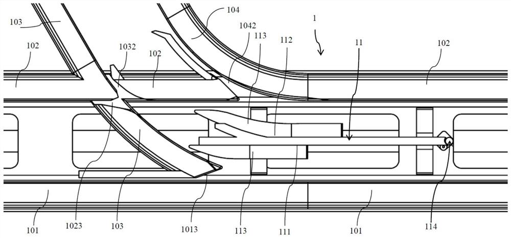
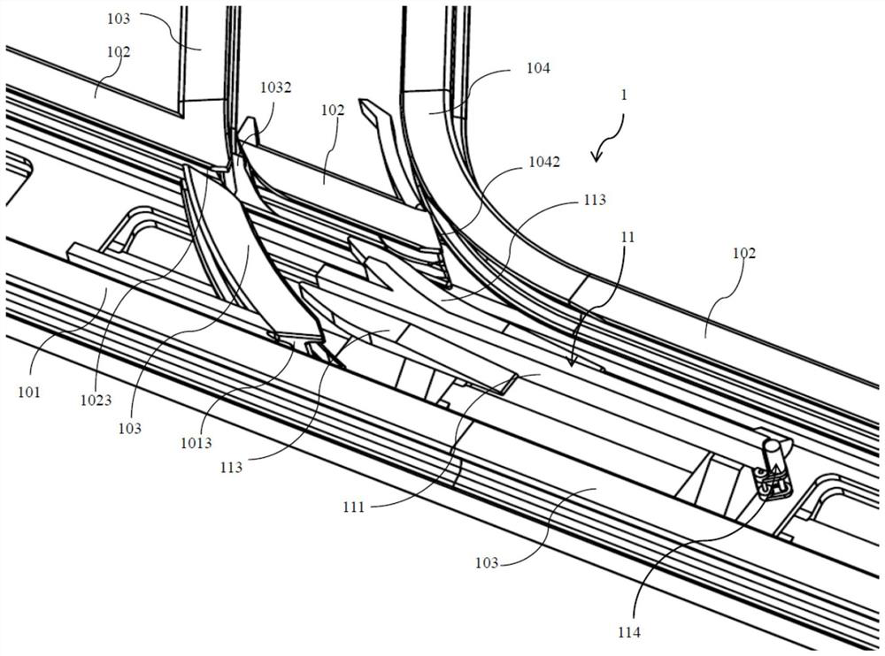
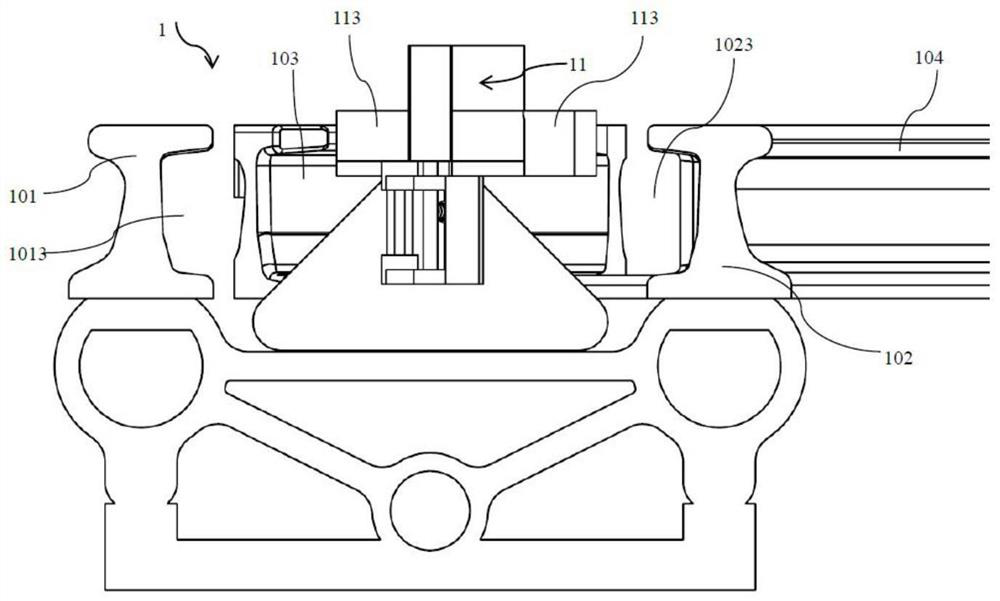
[0228] This embodiment provides a fixed switch track 1, including a switch structure and a branch guide rail 11 for guiding vehicles through the switch. The switch structure includes a main track and a branch track, and those skilled in the art can easily understand, Here, the main track and the branch track are just for the convenience of expression, and there is no difference in structure between the two.
[0229] Among them, such as Figure 1-Figure 4 and Figure 12-15 As shown, the main track includes a first main track 101 and a second main track 102, and the branch track includes a first branch track 103 and a second branch track 104, that is to say, the main track and The branch tracks are all double tracks. At the bifurcation, the second main rail 102 and the first bifurcation rail 103 are fixedly crossed at the bifurcation, and a rim groove 1023 along the inner edge direction of the second main rail 102 and a rim groove 1023 along the The rim groove 1032 in the dir...
Embodiment 2
[0237] On the structural basis of the fixed switch track 1 described in the above-mentioned embodiment 1, as Figure 5-Figure 10As shown (in order to reduce the number of drawings, refer to the drawings of Embodiment 3), the front end of the branch guide rail 11 is provided with a collision guide wheel assembly 114, and the collision guide wheel assembly 114 includes a support shaft 1145, which is rotatably mounted on The guide wheel 1142 on the top of the support shaft 1145 and the support shaft base 1141 . For the convenience of description, the support shaft base 1141 is divided into two parts, the base of the first area and the base of the second area. The base part of the zone protrudes from the front end of the branch guide rail 11, the lower part of the support shaft 1145 is installed on the base of the second zone, the front end of the branch guide rail 11 is a concave structure, and the branch guide rail 11 The concave structure at the front end of the rail 11 is in ...
Embodiment 3
[0240] On the structural basis of the fixed switch track 1 described in the above-mentioned embodiment 2, as Figure 5 to Figure 10 As shown, the support shaft base 1141 is provided with a micro-motion spring hole 1147 , a micro-motion spring 1144 of the support shaft base, a micro-motion support swing arm shaft 1146 and a micro-motion support swing arm 1143 . Such as Figure 6 As shown, one end of the micro-motion spring hole 1147 is closed and ends at the second rear of the base of the second area, and the second rear of the base of the second area is close to the second side of the bifurcated guide rail 11 In the guide rail portion 112 , the other end of the micro-motion spring hole 1147 is open and the opening extends toward the lower part of the support shaft 1145 . Such as Figure 6 and Figure 10 As shown, the support shaft base microspring 1144 is sleeved in the micro spring hole 1147, and one end of the support shaft base microspring 1144 is fixed on the closed end...
PUM
 Abstract
Description
Claims
Application Information
 - R&D
- Intellectual Property
- Life Sciences
- Materials
- Tech Scout
- Unparalleled Data Quality
- Higher Quality Content
- 60% Fewer Hallucinations
Browse by: Latest US Patents, China's latest patents, Technical Efficacy Thesaurus, Application Domain, Technology Topic, Popular Technical Reports.
© 2025 PatSnap. All rights reserved.Legal|Privacy policy|Modern Slavery Act Transparency Statement|Sitemap|About US| Contact US: help@patsnap.com


