
Lightning protection insulator with multi-column pie-shaped resistor discs connected in parallel

A technology of lightning protection insulators and resistors, which is applied in the direction of resistors, insulators, varistors, etc., can solve problems such as difficulty in improving the flow capacity, complicated construction, tripping and power failure of the line, etc., to achieve increased lightning protection flow capacity and production Easy to process and enhance absorption capacity

Inactive Publication Date: 2021-07-09
湖南防灾科技有限公司
View PDF4 Cites 0 Cited by
  • Summary
  • Abstract
  • Description
  • Claims
  • Application Information

AI Technical Summary

Problems solved by technology

In addition to overhead ground wires, arresters are generally used for lightning protection on transmission lines ("DL-T 815-2016 Metal Oxide Surge Arresters with Composite Jackets for AC Transmission Lines"), however, the existing arresters cannot withstand the tension of the wires, and installation requires Additional external mounting points are added, and the construction is complicated
At the same time, traditional surge arresters have limited flow capacity, and lightning strikes cause damage to zinc oxide arresters, which in turn cause line trips and power outages are still frequently reported
The core component of arrester lightning protection is the zinc oxide resistor. Enlarging the area of ​​the zinc oxide resistor can enhance the flow capacity, but it is difficult to produce a single piece of large-diameter zinc oxide resistor, and the inner surface of the annular zinc oxide resistor is under the action of the impact current. Concentration, the phenomenon of side flashover occurs, which makes it difficult to improve the flow capacity

Method used


Image

  • Lightning protection insulator with multi-column pie-shaped resistor discs connected in parallel
  • Lightning protection insulator with multi-column pie-shaped resistor discs connected in parallel
  • Lightning protection insulator with multi-column pie-shaped resistor discs connected in parallel

Examples


Embodiment Construction

[0029] In order to more clearly understand the above objects, features and advantages of the present disclosure, the solutions of the present disclosure will be further described below. It should be noted that, in the case of no conflict, the embodiments of the present disclosure and the features in the embodiments can be combined with each other.

[0030] In the following description, many specific details are set forth in order to fully understand the present disclosure, but the present disclosure can also be implemented in other ways than described here; obviously, the embodiments in the description are only some of the embodiments of the present disclosure, and Not all examples.

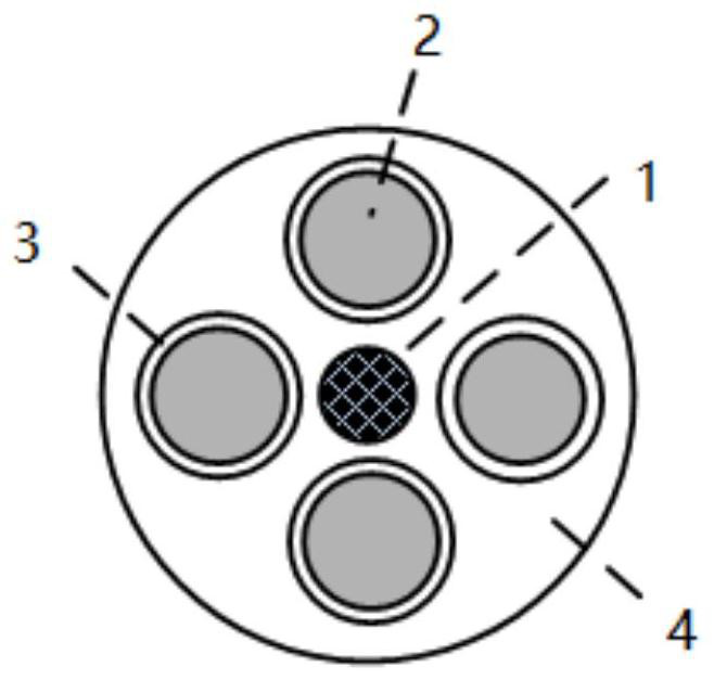
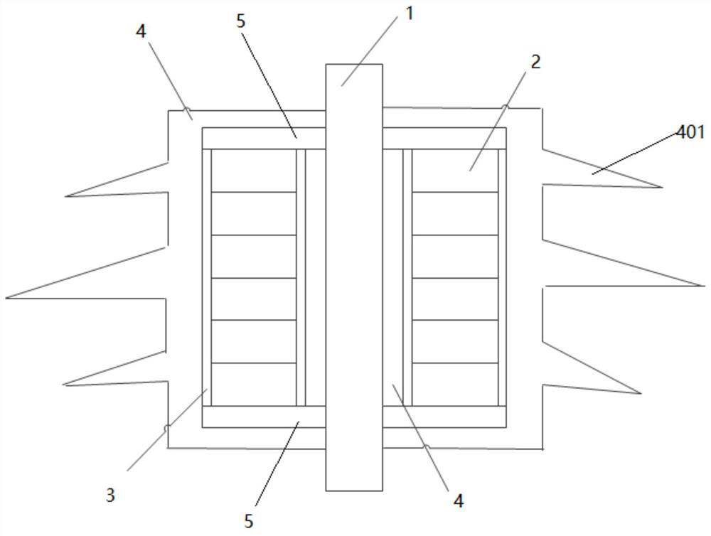
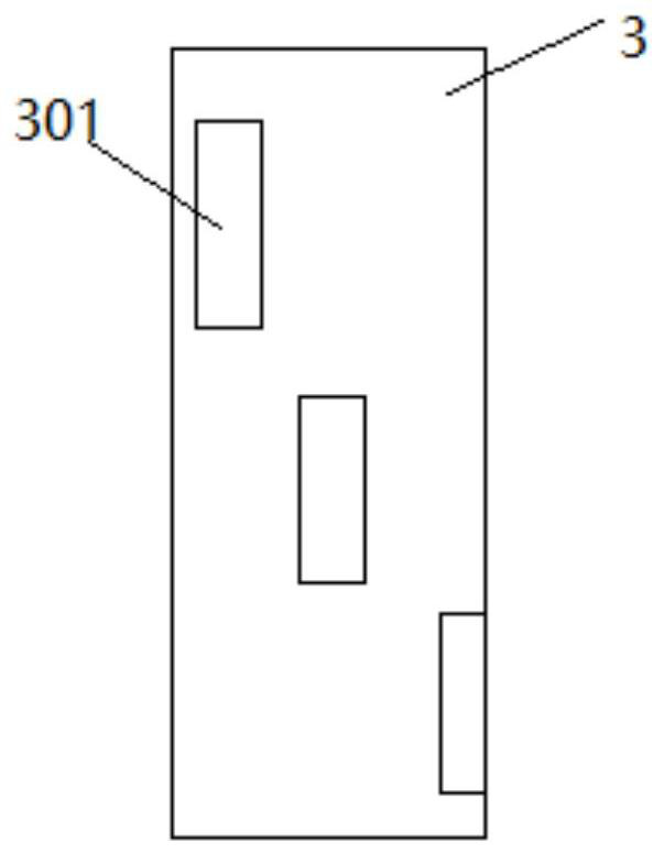
[0031] Such as figure 1 and figure 2 As shown, the present disclosure provides a lightning protection insulator with multi-column pie-shaped resistors connected in parallel, including an insulating post 4, an epoxy mandrel 1 and a parallel resistor, the epoxy mandrel 1 is embedded in the insul...


PUM


Abstract

The invention relates to the technical field of electrical engineering, in particular to a lightning protection insulator with multi-column cake-shaped resistor discs connected in parallel. The lightning protection insulator comprises an insulating column, an epoxy core rod and a parallel resistor, wherein the epoxy core rod is embedded in the insulating column; two ends of the epoxy core rod extend out of the insulating column, and the epoxy core rod has the capability of bearing wire tension; the parallel resistor comprises at least two voltage dependent resistor rods which are connected in parallel; and the at least two voltage dependent resistor rods are embedded in the insulating column and arranged around the epoxy core rod at intervals. The parallel resistor is in a high-resistance state under normal power frequency voltage, a resistance value is rapidly reduced when thunder and lightning act, thunder and lightning are discharged along the parallel resistor, and the resistance value is restored after the thunder and lightning, so power frequency current is extinguished. The parallel resistor can greatly improve the absorption capacity of thunder and lightning energy.

Description

technical field [0001] The disclosure relates to the technical field of electrical engineering, in particular to a lightning protection insulator with parallel connection of multi-column pie-shaped resistance pieces. Background technique [0002] In recent years, natural disasters have occurred frequently around the world, and transmission lines often suffer from tripping and power outages due to lightning strikes. With the rapid development of electric power construction, the area covered by the power grid is getting wider and wider, and transmission lines often need to be erected in some mountainous areas with complex terrain, and these areas often have climate phenomena that are prone to ice in winter and frequent lightning in spring and summer. In the above-mentioned areas with special geographical environment, when encountering severe weather, transmission lines are prone to flashover tripping and power outage accidents caused by lightning strikes, which seriously threa...

Claims


Application Information

Patent Timeline
IPC IPC(8): H01B17/46H01C7/12
CPCH01B17/46H01C7/123
Inventor 陆佳政谢鹏康李波熊蔚立胥望胡建平蒋正龙彭永晶
Owner 湖南防灾科技有限公司
Learn More