Scraper type chip removal device and chip removal method

A chip removal device and scraper-type technology, which is applied to metal processing machinery parts, maintenance and safety accessories, metal processing equipment, etc., can solve the problems of cutting fluid waste, etc., and achieve the effects of reducing carrying capacity, avoiding pollution, and reducing welding difficulty

Pending Publication Date: 2021-07-13
马鞍山昇工智能科技有限公司
View PDF1 Cites 2 Cited by
  • Summary
  • Abstract
  • Description
  • Claims
  • Application Information

AI Technical Summary

Problems solved by technology

[0006] Aiming at the problem that the cutting fluid is wasted along with the discharge of iron filings during the chip removal process of existing machine tools, the present invention designs a scraper type chip removal device and chip removal method. A chip retention section is set between the chip discharge ports to retain the chips, allowing the cutting fluid to flow back into the cutting fluid pool under the action of gravity, so as to avoid the waste of cutting fluid

Method used


Image

  • Scraper type chip removal device and chip removal method
  • Scraper type chip removal device and chip removal method
  • Scraper type chip removal device and chip removal method

Examples


Embodiment 1

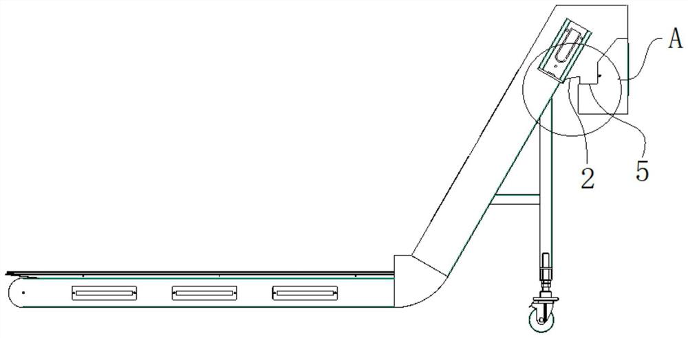
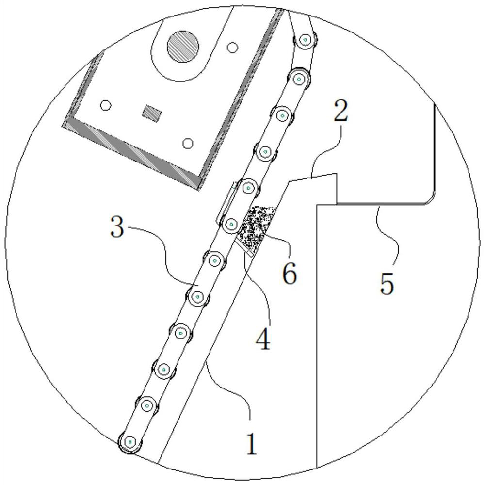
[0032] A scraper type chip removal device of this embodiment, such as figure 2 , 3 As shown, it includes a circulating scraper chain 3 and one end is fixedly connected to the circulating scraper chain 3, and the other end is close to several scrapers 4 of the chip removal climbing section 1; the chip removal climbing section 1 and A chip removal stagnation section 2 is arranged between the chip discharge outlets 5 .

[0033] A scraper type chip removal device in this embodiment makes full use of the adhesion difference between the cutting fluid and the iron filings 6 and the inclination angle of the scraper 4 in the conveying process, and the scraper 4 continuously scrapes the iron scraps 6 to the chip removal The accumulation on the retention section 2, the iron filings 6 accumulated on the chip removal retention section 2 are in the retention process, the cutting fluid breaks away from the iron filings 6 under the action of its own gravity and then flows back into the cutt...

Embodiment 2

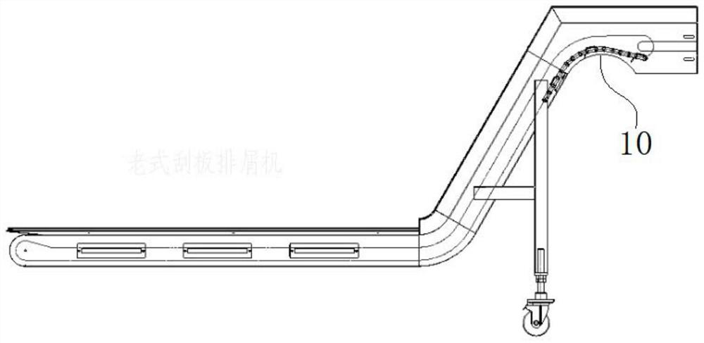
[0035] A scraper type chip removal device of this embodiment has the same basic structure as that of Embodiment 1, the differences and improvements are as follows: Figure 1 to Figure 7 As shown, the chip retention section 2 is slope-shaped, and the slope faces inward to allow the cutting fluid to flow inward and avoid outflow.

[0036] The scraper type chip removal device of this embodiment, through the existing such as figure 1 The arc surface section 10 at the top of the chip removal climbing section 1 shown (the purpose is to drop the iron filings in time as much as possible), is improved as figure 2 As shown in the slope surface structure, the upper part of the circulating scraper chain 3 does not need to be extended outward along the arc surface, and a certain height can be reserved directly along the direction of the original chip removal climbing section 1 for circulation. This is simple but ingenious The design has achieved unexpected technical effects: the length o...

Embodiment 3

[0038] A scraper type chip removal device of this embodiment has the same basic structure as that of Embodiment 2, the differences and improvements are as follows: Figure 1 to Figure 7 As shown, the slope angle is 0 to 60°, which is suitable for the separation of iron filings and cutting fluid. If it is too small, it will easily cause excessive accumulation and affect blanking. , and corresponding angle design can be carried out according to different iron filings 6 densities. Generally, the usual iron filings 6 have a slope of 10 to 20° most suitable. A further solution is that the edges on both sides of the chip removal climbing section 1 and the chip removal retention section 2 can be designed to be tilted upwards to form a structure with the warped edges upward, thereby forming a downward flow channel for the cutting fluid to prevent the cutting fluid from flowing along the sides. Spilling can also prevent iron filings from falling along the side.

[0039] The chip remov...


PUM


Abstract

The invention discloses a scraper type chip removal device and a chip removal method, and belongs to the technical field of machine tool machining matched equipment. The scraping plate type chip removal device comprises a circulating type scraper chain and a plurality of scrapers, wherein one ends of the scrapers are fixedly connected to the circulating type scraper chain, and the other ends of the scrapers are tightly attached to a chip removal climbing section; and a chip removal retention section is arranged between the chip removal climbing section and a chip removal discharging port. By fully utilizing the poor adhesive force between cutting fluid and scrap iron and the inclination angle of the scrapers in the conveying process, the cutting fluid is separated from the scrap iron under the action of the gravity of the cutting fluid and then flows back into a cutting fluid pool along the chip removal climbing section, the carrying amount of the cutting fluid during scrap iron falling is reduced, and therefore loss and waste of the cutting fluid are avoided, and the pollution to soil or environment caused by chemical components contained in the cutting fluid is also avoided.

Description

technical field [0001] The invention relates to the technical field of supporting equipment for machine tool processing, and more specifically relates to a scraper type chip removal device and a chip removal method. Background technique [0002] In the process of machine tool processing, semi-finished products will be processed, such as turning, milling, grinding, boring and other processes. During this process, iron chips will be generated, and metal chips and cutting fluid will be output from the machine tool outlet to chip removal. Machine (such as scraper chip removal machine), through the chip removal machine, metal chips will be generated during the working process of the metal machine tool, and the chips will be separated from the cutting fluid. [0003] In the chip removal process of the existing chip removal device, a certain amount of cutting fluid is more or less attached to the iron chips. During the chip removal process, the cutting fluid is discharged along wit...

Claims


Application Information

Patent Timeline
Patent Type & Authority Applications(China)
IPC IPC(8): B23Q11/00B23Q11/10
CPCB23Q11/0042B23Q11/1069
Inventor 陈安
Owner 马鞍山昇工智能科技有限公司
Why Eureka
Try Eureka