Bonding-wire-free LED patch support and welding method thereof

A LED patch and wire type technology, which is applied in the field of LED brackets, can solve problems such as low structural strength, reduced life of LED chips, and broken welding wires, and achieve the effect of enhancing the compressive capacity and structural strength

Active Publication Date: 2021-07-13
广东良友科技有限公司
View PDF8 Cites 0 Cited by
  • Summary
  • Abstract
  • Description
  • Claims
  • Application Information

AI Technical Summary

Problems solved by technology

[0005] Aiming at the deficiencies of the prior art, the present invention provides a wire-free LED patch bracket, which solves the problem that the above-mentioned current chip bracket needs to lead out the positive and negative poles of the chip through the bonding wire after the chip is fixed, and the chip The electrode is very small, and it is very easy to have the problem of virtual welding or welding wire breakage when welding the wire. At the same time, the body of the patch bracket is thin and its own structural strength is low. The bracket is easily damaged when it is squeezed, and the patch bracket is glued to the The chip is fixed, and there is no reflective material around it. When the chip emits light, part of the light is absorbed by the surrounding baffles, and the luminous efficiency of the chip is seriously affected. When the chip is mounted, the LED bracket mostly fixes the LED chip with glue, and the heat dissipation effect of the fixing glue is not good. The problem that the life of the LED chip will be seriously reduced due to the use of the chip under the condition of excessive temperature

Method used


Image

  • Bonding-wire-free LED patch support and welding method thereof
  • Bonding-wire-free LED patch support and welding method thereof
  • Bonding-wire-free LED patch support and welding method thereof

Examples


Embodiment Construction

[0032] Embodiments of the present invention are described in detail below, examples of which are shown in the drawings, wherein the same or similar reference numerals denote the same or similar elements or elements having the same or similar functions throughout. The embodiments described below by referring to the figures are exemplary only for explaining the present invention and should not be construed as limiting the present invention.

[0033]In describing the present invention, it should be understood that the terms "center", "longitudinal", "transverse", "length", "width", "thickness", "upper", "lower", "front", " Orientation indicated by rear, left, right, vertical, horizontal, top, bottom, inside, outside, clockwise, counterclockwise, etc. The positional relationship is based on the orientation or positional relationship shown in the drawings, which are only for the convenience of describing the present invention and simplifying the description, rather than indicating ...


PUM


Abstract

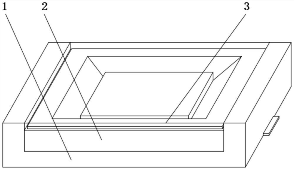
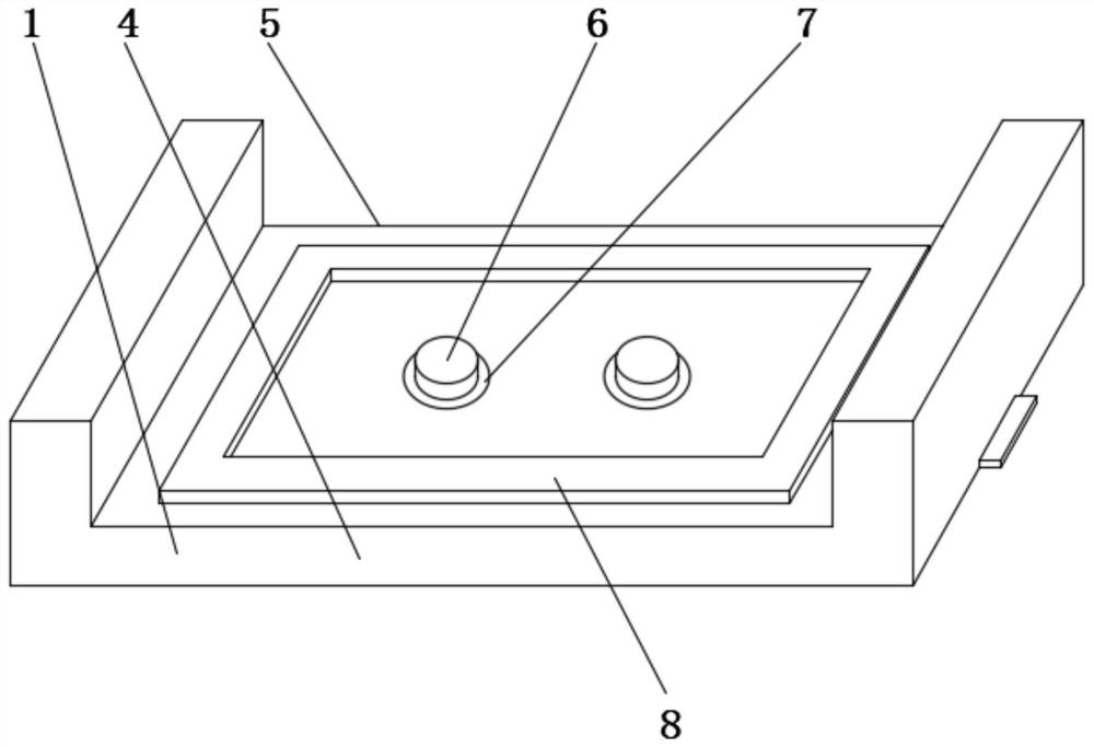
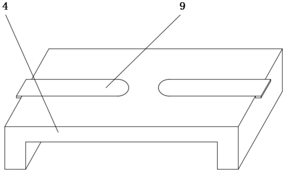
The invention provides a bonding-wire-free type LED patch support and a welding method thereof. The bonding-wire-free type LED patch support comprises a protection base, the protection base comprises a base body, a support mounting groove, solder paste, a metal electrode, hot melt adhesive and a conductive electrode slice, the support mounting groove is formed in the upper end face of the base body, the hot melt adhesive is fixedly connected to the bottom of the support mounting groove, the metal electrode is fixedly connected to the bottom of the support mounting groove, the solder paste is fixedly connected to the upper end face of the metal electrode, the conductive electrode plate is fixedly connected to the lower end face of the base body, the support is fixedly connected to the upper end face of the protection base, and the support comprises a support body, a limiting groove, a reflector, a chip, a chip mounting groove, an electrode groove and a cooling groove. The limiting groove is formed in the upper end face of the support body, the chip mounting groove is formed in the bottom of the limiting groove, the structural strength of the support is effectively improved, meanwhile, the refraction capacity of the support is improved, and the luminous efficiency of an LED chip is higher.

Description

technical field [0001] The invention relates to the technical field of LED brackets, in particular to a wire-free LED patch bracket and a welding method thereof. Background technique [0002] LED light-emitting diode is a solid-state semiconductor device that can directly convert electrical energy into light energy. The heart of the LED is a semiconductor chip. One end of the chip is attached to a bracket, which is the negative pole, and the other end is connected to the positive pole of the power supply. Whole chip is encapsulated by epoxy resin, and semiconductor chip is made up of two parts, and a part is P-type semiconductor, and hole occupies an leading position in it, and the other end is N-type semiconductor, is mainly electron here, but these two kinds of semiconductors When they are connected, a "P-N junction" is formed between them. When the electric current acts on the wafer through the wire, the electrons will be pushed to the P region, where the electrons recomb...

Claims


Application Information

Patent Timeline
IPC IPC(8): H01L33/48H01L33/62H01L33/64
CPCH01L33/483H01L33/62H01L33/647H01L33/64H01L2933/0033
Inventor 戴高潮
Owner 广东良友科技有限公司
Why Eureka
Try Eureka