Anti-fouling device for optical fiber sensor

An optical fiber sensor and anti-fouling technology, which is applied in the direction of grinding/polishing safety devices, grinding/polishing equipment, grinding machine parts, etc., can solve the problems of limited detection function, interference signal detection, dust generation, etc., to prevent Pollution, compact layout, and stable rust-proof performance

Active Publication Date: 2021-07-16
沈阳和研科技股份有限公司
View PDF9 Cites 2 Cited by
  • Summary
  • Abstract
  • Description
  • Claims
  • Application Information

AI Technical Summary

Problems solved by technology

However, there will be the following problems during use: the cutting cooling water sprays on the high-speed rotating blade and becomes water mist to fill the cutting cavity, and also fills between the signal transmitting end and the signal receiving end of the optical fiber sensor, which interferes with the detection of the signal. Cause machine misjudgment; cutting will also produce dust, mixed with water mist to become sewage flooding around the high-speed rotating blade, after a period of time, it will adhere to the prism of the sensor, blocking the optical signal, which seriously limits the application of the detection function ;

Method used


Image

  • Anti-fouling device for optical fiber sensor
  • Anti-fouling device for optical fiber sensor
  • Anti-fouling device for optical fiber sensor

Examples


Embodiment 1

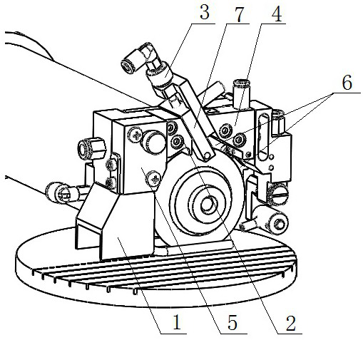
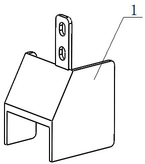
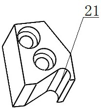
[0028] The invention provides an antifouling device for optical fiber sensors, which is in a semi-enclosed structure, see Figure 1-7 , including: fog collecting deflector 1, sewage intercepting plate 2, longitudinal air blowing assembly 3, horizontal air blowing assembly 4, front water spraying plate 5 and rear bottom plate 6;

[0029] The mist-collecting deflector 1 is arranged on the front water spray plate 5, and is located below the front water spray plate 5; On the rear bottom plate 6, and the front water spray plate 5, the sewage interceptor plate 2, the longitudinal air blowing assembly 3 and the horizontal air blowing assembly 4 are arranged in sequence from left to right;

[0030] Wherein, the optical fiber sensor 7 is arranged on the longitudinal air blowing assembly 3 .

[0031] Further, see Figure 4 , 5 , the longitudinal blowing assembly 3 includes: a longitudinal blowing main body 31 and a longitudinal blowing joint 32 arranged on the longitudinal blowing ma...


PUM


Abstract

The invention relates to a grinding wheel scribing machine, and provides an anti-fouling device for an optical fiber sensor. The device is of a semi-enclosed structure and comprises a fog collecting guide plate, a sewage intercepting plate, a longitudinal air blowing assembly, a transverse air blowing assembly, a front water spraying plate and a rear bottom plate. The fog collecting guide plate, the sewage intercepting plate, the longitudinal air blowing assembly, the transverse air blowing assembly and the front water spraying plate are all arranged on the rear bottom plate. The fog collecting guide plate is arranged below the front water spraying plate, and the front water spraying plate, the sewage intercepting plate, the longitudinal air blowing assembly and the transverse air blowing assembly are sequentially arranged from left to right. The optical fiber sensor is arranged on the longitudinal air blowing assembly. By adoption of the device, pollution of water flow to the sensor can be prevented, and the bidirectional air blowing structure can also prevent pollution of water mist spreading in the space to the sensor.

Description

technical field [0001] The invention relates to a grinding wheel dicing machine, and in particular provides an antifouling device for an optical fiber sensor. Background technique [0002] Grinding wheel dicing machine is a precision CNC cutting equipment that integrates technologies such as water, gas, electricity, air static pressure high-speed spindle, precision mechanical transmission, sensors and automatic control. The core components of the cutting unit are the spindle and the blade. The state of the blade during cutting directly affects the cutting effect. In order to ensure the stability of the cutting effect, the machine needs to detect the real-time state of the blade. The method is to install an optical fiber sensor on both sides of the blade. The changes in the signals received by the sensors are used to infer the real-time status of the blades. However, there will be the following problems during use: the cutting cooling water sprays on the high-speed rotating ...

Claims


Application Information

Patent Timeline
Patent Type & Authority Applications(China)
IPC IPC(8): B24B27/06B24B41/04B24B55/00
CPCB24B27/0683B24B41/04B24B55/00
Inventor 袁慧珠刘苏阳刘佳梦秦瀚林杨盛高永霖
Owner 沈阳和研科技股份有限公司
Why Eureka
Try Eureka