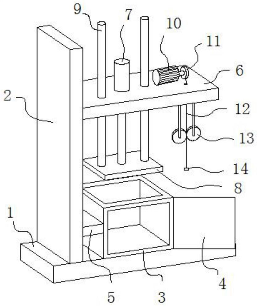
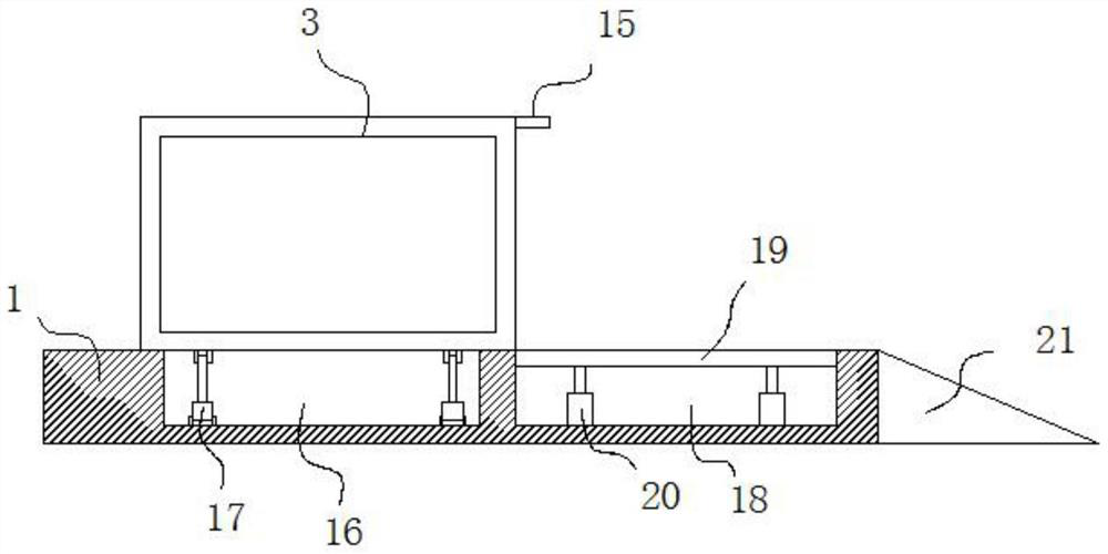
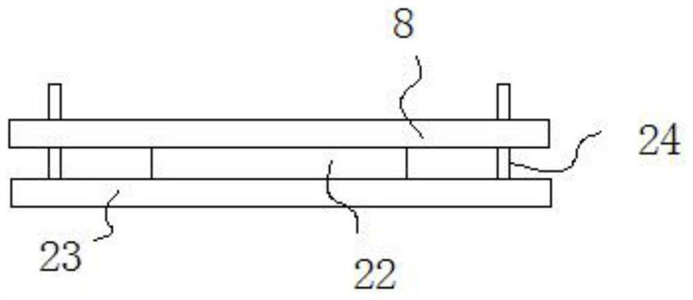
Waste treatment equipment for part machining

A technology for processing equipment and waste, which is applied in the field of parts processing, can solve the problems of large impact force of hydraulic cylinders, affect efficiency, and low efficiency, and achieve the effects of avoiding directional impact, improving efficiency, and ensuring quality

Active Publication Date: 2021-07-16
AVIC POWER ZHUZHOU AVIATION PARTS MFG
View PDF8 Cites 0 Cited by
  • Summary
  • Abstract
  • Description
  • Claims
  • Application Information

AI Technical Summary

Problems solved by technology

[0003] During the processing of existing mechanical parts, a large amount of waste is often generated. The waste can be recycled, but the scattered waste needs to be integrated, so waste treatment equipment needs to be used. The existing waste The treatment equipment uses the hydraulic cylinder to drive the pressure plate to press the fragmented waste to form a whole piece of waste, which is convenient for transportation and recycling. However, in the process of using the existing waste treatment equipment, manual labor is often required. After the waste is collected, it is transported to the processing equipment by a trolley, and then the waste is manually put into the equipment. The manual labor is large and the efficiency is low. In addition, the existing equipment is used to compress different amounts of waste. The whole time is often manually controlled, and the pressure control is not precise. If the pressure is too high, it will easily cause a large reverse impact on the hydraulic cylinder. At the same time, when the pressure is small, it will often appear loose. Use the push plate to push it out, and then transfer it to the transfer vehicle, but after the whole piece of waste is pushed out, it fits the ground, and it still needs to be hoisted again by lifting equipment before loading, which brings some troubles to the operation. affect efficiency

Method used


Image

  • Waste treatment equipment for part machining
  • Waste treatment equipment for part machining
  • Waste treatment equipment for part machining

Examples


Embodiment Construction

[0025] The following will clearly and completely describe the technical solutions in the embodiments of the present invention with reference to the accompanying drawings in the embodiments of the present invention. Obviously, the described embodiments are only some, not all, embodiments of the present invention.

[0026] In describing the present invention, it should be understood that the terms "upper", "lower", "front", "rear", "left", "right", "top", "bottom", "inner", " The orientation or positional relationship indicated by "outside", etc. is based on the orientation or positional relationship shown in the drawings, and is only for the convenience of describing the present invention and simplifying the description, rather than indicating or implying that the referred device or element must have a specific orientation, so as to Specific orientation configurations and operations, therefore, are not to be construed as limitations on the invention.

[0027] In the description...


PUM


Abstract

The invention belongs to the field of part machining, and particularly relates to waste treatment equipment for part machining. The waste treatment equipment comprises a base, a supporting plate is fixedly installed on the left side of the top of the base, a top plate is fixedly connected to the right side wall of the supporting plate, a first hydraulic cylinder is fixedly installed in the middle of the top of the top plate, and a piston rod of the first hydraulic cylinder penetrates through the top plate and is fixedly connected with a first pressing plate. According to the waste treatment equipment, a winding reel can be driven by a motor to wind a steel wire rope, so that a trolley for conveying waste can be pulled to a lifting plate; and then after the lifting plate is lifted, the front end of the trolley is clamped on a convex block, the tail of the trolley is pulled by utilizing the steel wire rope again, then the trolley can rotate along the convex block, the waste can be directly guided into a box body, so that manpower is greatly saved, manual feeding is not needed, and the efficiency is effectively improved.

Description

technical field [0001] The invention relates to the field of parts processing, in particular to waste treatment equipment for parts processing. Background technique [0002] Since the emergence of machinery, there have been corresponding mechanical parts. But as a discipline, mechanical parts are separated from mechanical construction and mechanics. With the development of the machinery industry, the emergence of new design theories and methods, new materials, and new processes, mechanical parts have entered a new stage of development. Theories such as finite element method, fracture mechanics, elastohydrodynamic lubrication, optimization design, reliability design, computer-aided design (CAD), solid modeling (Pro, Ug, Solidworks, etc.), system analysis and design methodology have gradually For research and design of mechanical parts. To better realize the synthesis of multiple disciplines, to realize the combination of macro and micro, to explore new principles and struc...

Claims


Application Information

Patent Timeline
Patent Type & Authority Applications(China)
IPC IPC(8): B30B9/00B30B15/30B30B15/32B30B15/00B66C23/20
CPCB30B9/00B30B15/30B30B15/32B30B15/00B66C23/202Y02W30/58
Inventor 陈刚王熔
Owner AVIC POWER ZHUZHOU AVIATION PARTS MFG
Why Eureka
Try Eureka