Biomass and coal co-gasification system and method

A biomass and co-gasification technology, applied in the field of gasification, can solve the problems of limiting biomass, pipeline blockage, and low gasification temperature, and achieve the effects of increasing the proportion of mesopores, promoting conversion, and improving gasification efficiency

Active Publication Date:
View PDF16 Cites 0 Cited by
  • Summary
  • Abstract
  • Description
  • Claims
  • Application Information

AI Technical Summary

Problems solved by technology

By gasification of biomass, fuel gas can also be obtained. However, the conventional gasification temperature of biomass is relatively low, resulting in a large amount of tar in the gas for gasification of biomass, which will easily lead to blockage of pipelines after condensation, which limits the use of biomass. Development of Sole Gasification

Method used


Image

  • Biomass and coal co-gasification system and method
  • Biomass and coal co-gasification system and method
  • Biomass and coal co-gasification system and method

Examples


Embodiment 1

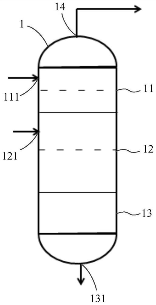
[0048] refer to figure 1 As shown, this embodiment provides a biomass and coal co-gasification system, the system specifically includes a gasifier 1 . The gasifier 1 is specifically a fluidized bed gasifier. The inner cavity of the gasifier 1 includes a pyrolysis zone 11 , a gasification zone 12 and a combustion zone 13 in sequence from top to bottom. It should be noted that the description from top to bottom here is based on the state of the gasifier 1 during specific use.

[0049] The pyrolysis zone 11 has a coal sample inlet 111 through which the coal sample can enter, so that the coal sample undergoes a pyrolysis reaction in the pyrolysis zone 11 to generate pyrolysis gas and pyrolysis tar. Among them, the gasification zone 12 is communicated with the pyrolysis zone 11, and the pyrolysis semi-coke produced by the reaction in the pyrolysis zone 11 can enter the gasification zone 12 from the pyrolysis zone 11, and the gasification zone 12 has a raw material for biomass to ...

Embodiment 2

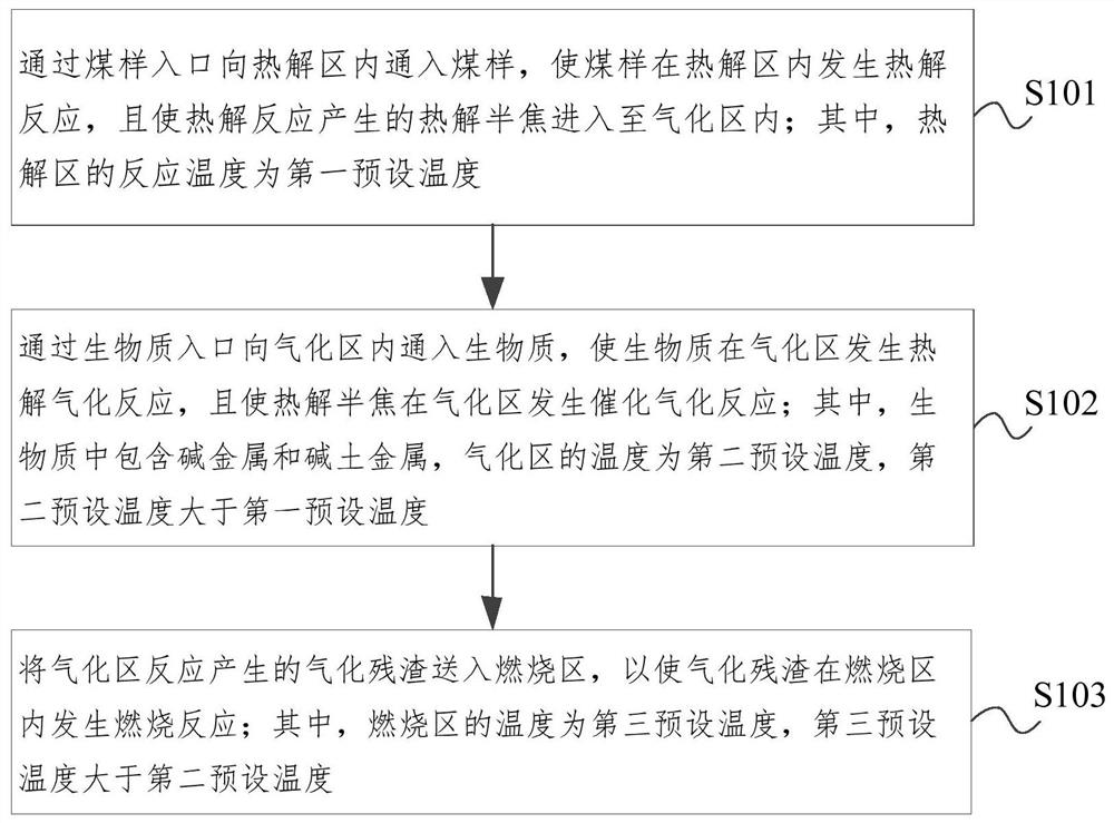
[0071] image 3 This is a schematic flowchart of the method for co-gasification of biomass and coal according to the embodiment of the present disclosure. refer to image 3 As shown, this embodiment also provides a method for co-gasification of biomass and coal, and the method can be implemented by part or all of the co-gasification system of biomass and coal provided in the above embodiment, so as to realize the co-gasification of biomass and coal. Co-gasification not only realizes the gasification of coal and biomass, but also plays the role of a catalyst in biomass, provides a cheap and disposable catalyst for coal gasification, and promotes the conversion of coal. produces tar.

[0072] combine Figure 1 to Figure 3 As shown, the method for the co-gasification of biomass and coal will be described below through specific embodiments, and the method specifically includes:

[0073] S101. Pass the coal sample into the pyrolysis zone through the coal sample inlet, so that t...


PUM


Abstract

The disclosure relates to a biomass and coal co-gasification system and method. The system includes a gasification furnace, and the inner chamber of the gasification furnace includes a pyrolysis zone, a gasification zone, and a combustion zone from top to bottom; the pyrolysis zone has The coal sample inlet, the gasification area is connected with the pyrolysis area, and the pyrolysis semi-coke produced by the reaction in the pyrolysis area can enter the gasification area. The gasification area has a biomass inlet, and the combustion area is connected with the gasification area to make the gasification The gasification residue produced by the reaction in the gasification zone enters the combustion zone for combustion reaction; the bottom of the combustion zone has an ash outlet, and the ash contains potassium element; the top of the gasifier has a gas outlet, which not only realizes coal gasification Gasification and biomass gasification, and the alkali metals and alkaline earth metals in the biomass also play a catalytic role on coal, providing a cheap and disposable catalyst for coal gasification, improving the gasification efficiency, and the process will not Produces tar.

Description

technical field [0001] The present disclosure relates to the technical field of gasification, and in particular, to a system and method for co-gasification of biomass and coal. Background technique [0002] Due to China's "coal-rich, gas-poor and oil-poor" energy structure, the natural gas content cannot meet domestic demand. Coal gasification has become an important way to alleviate the shortage of domestic natural gas, and cheap and highly active catalysts have become a key factor restricting the development of coal gasification. [0003] There is a huge amount of biomass available in my country, and biomass is rich in alkali metals and alkaline earth metals, which is a huge catalyst resource. Gas can also be obtained by gasifying biomass. However, the conventional gasification temperature of biomass is low, resulting in a large amount of tar in the gas gasified by biomass gasification. After condensation, it is easy to cause blockage of pipelines, which limits biomass T...

Claims


Application Information

Patent Timeline
Patent Type & Authority Patents(China)
IPC IPC(8): C10J3/60C10J3/84
CPCC10J3/60C10J3/84
Inventor 孙志强王会芳李克忠刘雷李鹏
Why Eureka
Try Eureka