Lap joint injection molding type connecting assembly and steel bar truss floor support plate

A technology for connecting components and steel trusses, which is applied to floors, building components, buildings, etc. It can solve the problems that the bottom of the floor cannot meet the acceptance criteria, affect the appearance of the bottom of the floor, increase the deformation of the bottom of the bottom form, and improve the disassembly efficiency. , good flatness of the bottom of the board, and the effect of reducing the difficulty of disassembly

Pending Publication Date: 2021-07-16
DUOWEI UNION GRP
View PDF0 Cites 2 Cited by
  • Summary
  • Abstract
  • Description
  • Claims
  • Application Information

AI Technical Summary

Problems solved by technology

However, there are three deficiencies: 1) The steel bar trusses and connectors are fastened. During the construction stage of the floor deck, the steel bar trusses and the connectors can slide, and this sliding will increase the deformation at the bottom of the bottom formwork. As a result, the flatness of the bottom of the floor slab after forming may not meet the acceptance criteria; 2) After the bottom formwork is removed, the connectors are directly exposed to the outside and directly in contact with the air, resulting in corrosion of the connectors, which affects the appearance of the bottom of the floor slab ; 3) After the existing screws are connected with the connectors, the screws usually expose a part. When pouring concrete on the bottom form, the concrete will wrap the screws, increasing the difficulty of disassembling the bottom form
However, after the existing floor decks are spliced, when the concrete is poured, due to the weight of the concrete or the impact load when pouring the concrete, misalignment will occur between the two floor decks on both sides of the splicing joint, making Poured floors are uneven

Method used


Image

  • Lap joint injection molding type connecting assembly and steel bar truss floor support plate
  • Lap joint injection molding type connecting assembly and steel bar truss floor support plate
  • Lap joint injection molding type connecting assembly and steel bar truss floor support plate

Examples


Embodiment 1

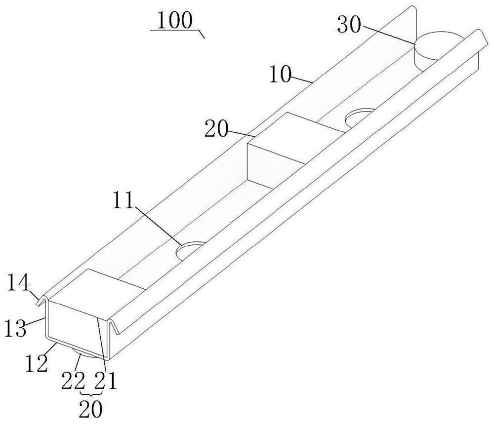
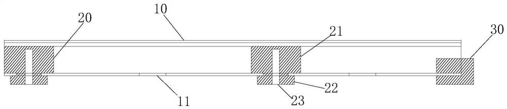
[0061] figure 1 It is a three-dimensional structural schematic diagram of an overlapping injection molding connection assembly in an embodiment of the present invention, figure 2 It is a schematic cross-sectional structure diagram of an overlapping injection molding connection assembly in an embodiment of the present invention, such as figure 1 and figure 2 shown.

[0062] An embodiment of the present invention provides an overlapping injection molding connection assembly 100 , including: a connecting piece 10 , a bridging piece 30 and a supporting piece 20 . Wherein, the connector 10 has a first surface and a second surface opposite to each other, and has a mounting hole 11 penetrating through the first surface and the second surface. by figure 1 and figure 2 Take the orientation in , as an example, the first side is the upward side, and the second side is the downward side.

[0063] combine figure 1 and figure 2 , see Figure 3 to Figure 5 , the supporting membe...

Embodiment 2

[0114] On the basis of Example 1, combined with Figure 6 , see Figure 11 and Figure 12 Correspondingly, the embodiment of the present invention also provides a reinforced truss floor deck, including: a floor deck body 200 , a plurality of rows of overlapping connection assemblies 100 and a steel truss 300 .

[0115] Wherein, each row of overlapping connecting assemblies 100 includes a plurality of overlapping connecting assemblies 100 arranged at intervals. The overlapping connection assembly 100 can be realized by the overlapping connection assembly 100 described in the embodiments. Specifically, see Figure 1 to Figure 5 , The overlapping connection assembly 100 includes: a connecting piece 10 , a connecting piece 30 and a supporting piece 20 . The connector 10 has a first surface and a second surface opposite to each other, and has a mounting hole 11 passing through the first surface and the second surface. The supporting member 20 is passed through the mounting hol...


PUM


Abstract

The embodiments of the invention provide a lap joint injection molding type connecting assembly and a steel bar truss floor support plate. The lap joint injection molding type connecting assembly comprises a connecting piece, lap joint pieces and a supporting piece, the connecting piece is provided with a first surface, a second surface and a mounting hole, wherein the first face and the second face are oppositely arranged, and the mounting hole penetrates through the first face and the second face; the lap joint pieces are arranged at at least one end of the connecting piece, and at least part of the lap joint pieces abuts against the second face; the supporting piece penetrates through the mounting hole and is connected to the connecting piece in an injection molding mode; and the supporting piece comprises a clamping head and a supporting seat, the clamping head abuts against the first face, the supporting seat abuts against the second face, and a connecting hole is formed in the supporting seat. The height of the connecting piece is increased through the supporting piece, a fastening piece is wrapped, so that concrete can enter the bottom of the connecting piece more easily, corrosion caused by exposure of the connecting piece is avoided, the concrete is prevented from making contact with the fastening piece, the fastening piece dismounting efficiency is improved, the lap joint pieces are arranged on the adjacent floor support plate bodies in a lap joint mode, dislocation of splicing seams between the adjacent floor support plate bodies is avoided, and the flatness of floor slabs is guaranteed.

Description

technical field [0001] The embodiments of the present invention relate to the technical field of construction, in particular to an overlapping injection-molded connection assembly and a reinforced truss floor deck. Background technique [0002] With the continuous development of the construction industry, detachable steel truss floor decks are gradually being used in various buildings, such as residential buildings. The detachable steel truss floor deck speeds up the construction progress, reduces the temporary support for construction, enables rapid installation, and reuses the formwork. [0003] In the traditional technology, the steel bar truss of the detachable steel bar truss floor deck is connected to the bottom form by a connecting piece, and the connecting piece and the bottom form are connected by screws. However, there are three deficiencies: 1) The steel bar trusses and connectors are fastened. During the construction stage of the floor deck, the steel bar trusse...

Claims


Application Information

Patent Timeline
Patent Type & Authority Applications(China)
IPC IPC(8): E04B5/17E04B1/38E04B1/61
CPCE04B5/17E04B1/61E04B1/388
Inventor 陶红斌孙刚张赞王保强
Owner DUOWEI UNION GRP
Why Eureka
Try Eureka