Power output device

A technology of power output and transmission sprocket, which is applied in the direction of mechanical power generating mechanisms, machines/engines, mechanical equipment, etc., can solve the problems of large environmental impact, large fuel consumption, etc., and achieve the effect of reducing environmental pollution

Inactive Publication Date: 2021-07-16
凌宏一
View PDF0 Cites 0 Cited by
  • Summary
  • Abstract
  • Description
  • Claims
  • Application Information

AI Technical Summary

Problems solved by technology

[0003] Aiming at the deficiencies of the prior art, the object of the present invention is to provide a power output device, which can solve the problems of large fuel consumption and great impact on the environment of the existing coal generating sets and other transmission devices

Method used


Image

  • Power output device

Examples


Embodiment Construction

[0014] Below, in order to make the purpose, technical solutions and advantages of the present invention more clear, the present invention will be further described in conjunction with the accompanying drawings and specific embodiments. It should be understood that the specific embodiments and parameters described here are only used for The present invention is explained, not intended to limit the present invention.

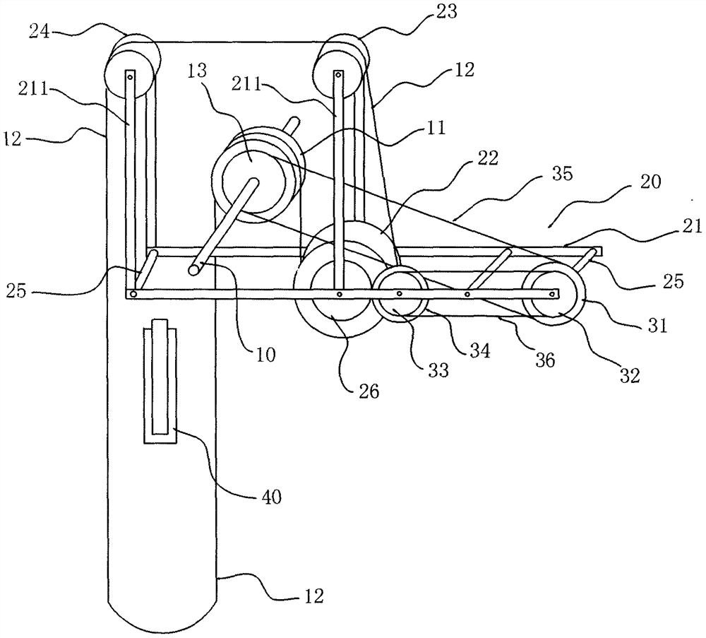
[0015] see figure 1 , which is a schematic diagram of the overall structure of a power output device of the present invention, which includes a frame (not shown), a main shaft 10 , a support frame 20 and a transmission assembly 30 .

[0016] see figure 1 , the main shaft 10 is pivotally connected to the frame through bearings, and the main shaft 10 is synchronously connected with a running wheel 11 and a driving sprocket 13. The wheel circumference of the wheel 11 is provided with a rope groove, and a gravity circulation rope 12 is suspended on the rope groove o...


PUM


Abstract

The invention discloses a power output device, in particular to machinery for converting gravity into rotating power. A drive shaft is driven to rotate and output power outwards through effect of gravity difference between left and right sides of a rotary wheel, and a power generator is driven to generate power, so that consumption of energy such as coals, petroleum and natural gas can be reduced; and harmful substances are not discharged into the atmospheric environment, so that environmental pollution is reduced.

Description

technical field [0001] The invention relates to the technical field of machinery, in particular to a power output device. Background technique [0002] With the gradual deterioration of the natural environment and the increasing shortage of energy, people's requirements for energy-saving and environmentally friendly mechanical power output devices are gradually increasing. The current generators usually use coal as energy, and the coal is burned to drive the generator set. Generator sets generate electricity at high speeds to convert coal into electricity. However, this method has a relatively low energy utilization rate, and during the combustion of coal, a large amount of harmful substances are emitted into the atmosphere, which is harmful to the environment. Pollution is relatively large. In addition, some use solar power generation. Although solar power generation can solve the problem of environmental pollution and is a sustainable renewable energy source, the use of s...

Claims


Application Information

Patent Timeline
IPC IPC(8): F03G7/10
CPCF03G7/10
Inventor 凌宏一凌远峰
Owner 凌宏一
Why Eureka
Try Eureka