Scrap collecting robot for numerical control metal cutting machine tool and scrap collecting method
A metal cutting and robotic technology, applied in metal processing machinery parts, metal processing equipment, maintenance and safety accessories, etc., can solve problems such as unfavorable promotion and use, affecting collection effect, etc., to save manpower, increase collection effect, and facilitate cleaning. Effect
- Summary
- Abstract
- Description
- Claims
- Application Information
AI Technical Summary
Problems solved by technology
Method used
Image

Examples
Embodiment 1
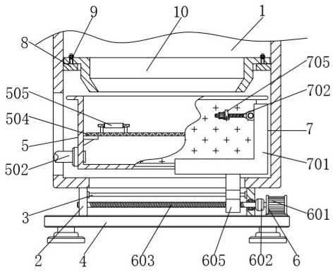
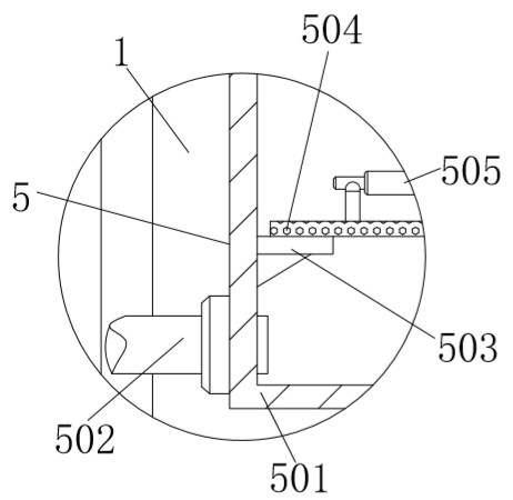
[0033] A waste chip collection robot for CNC metal cutting machine tools, comprising a lathe 1, a vertical plate 2, a guide rod 3 and a base 4, vertical plates 2 are fixedly connected to the left and right sides of the lower surface of the lathe 1, the lathe 1 is a CNC lathe, and the two A guide rod 3 is arranged between each vertical board 2, and the left and right sides of the guide rod 3 are fixedly connected with the vertical board 2, the bottom end of the vertical board 2 is fixedly connected with a base 4, and a collection mechanism 5 is installed inside the lathe 1, The collection mechanism 5 includes a collection box 501, a liquid outlet pipe 502, a support plate 503, a net plate 504, and a handle 505. The outer wall of the collection box 501 is matched with the inner cavity of the lathe 1, and the left bottom of the collection box 501 is sleeved with a liquid outlet. Pipe 502, the liquid outlet pipe 502 pours out the cutting fluid in the collection box 501, the outer w...
Embodiment 2
[0035] As an option, see Figure 6 , a waste chip collection robot for a CNC metal cutting machine tool, an annular plate 8 is provided at the bottom of the inner cavity of the lathe 1, the outer wall of the annular plate 8 is fixedly connected to the inner cavity of the lathe 1, and an inner shell 9 is sleeved on the inner wall of the annular plate 8, The outer wall of the inner shell 9 is in clearance fit with the inner wall of the annular plate 8, and the left and right sides of the inner shell 9 are socketed with bolts 10, and the outer walls of the two bolts 10 are in clearance fit with the inner through hole of the inner shell 9. The bottom is conical, and the bottom end of the latch 10 is affixed to the upper surface of the annular plate 8 , and the two inserting rods 10 fix the position of the inner shell 9 in the annular plate 8 .
[0036] The solution in this embodiment can be selectively used in combination with the solutions in other embodiments.
Embodiment 3
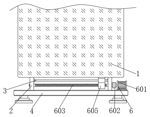
[0038] As an option, see figure 1 , 2 And 4, a waste collection robot for a CNC metal cutting machine tool, a power mechanism 6 is fixedly connected to the right side of the upper surface of the base 4, and the power mechanism 6 includes a motor 601, a shaft coupling 602, a threaded rod 603, a bearing 604 and a slider 605, The bottom end of the motor 601 is affixed to the base 4, and the left end of the output shaft of the motor 601 is affixed to a coupling 602. The output shaft of the motor 601 is affixed to the threaded rod 603 through the coupling 602, and the motor 601 is connected to the threaded rod 603 through the coupling. 602 drives the threaded rod 603 to rotate, the outer wall of the threaded rod 603 is provided with a bearing 604, the outer wall of the threaded rod 603 is movably connected with the vertical plate 2 through the bearing 604, the outer wall of the threaded rod 603 is threadedly connected with a slide block 605, and the inside of the slide block 605 is...
PUM
 Abstract
Description
Claims
Application Information
 - Generate Ideas
- Intellectual Property
- Life Sciences
- Materials
- Tech Scout
- Unparalleled Data Quality
- Higher Quality Content
- 60% Fewer Hallucinations
Browse by: Latest US Patents, China's latest patents, Technical Efficacy Thesaurus, Application Domain, Technology Topic, Popular Technical Reports.
© 2025 PatSnap. All rights reserved.Legal|Privacy policy|Modern Slavery Act Transparency Statement|Sitemap|About US| Contact US: help@patsnap.com