
Printed matter surface film laminating equipment

A technology for printing and laminating, applied in the field of laminating equipment on the surface of printed matter, can solve the problems affecting the lamination efficiency of cardboard, and achieve the effects of improving lamination efficiency, reducing waste and reducing labor intensity

Active Publication Date: 2021-07-23
杭州美利建印刷有限公司
View PDF12 Cites 6 Cited by
  • Summary
  • Abstract
  • Description
  • Claims
  • Application Information

AI Technical Summary

Problems solved by technology

[0004] In view of the above-mentioned related technologies, the inventor believes that there are the following defects: after the cardboard is covered with film, because the film is a whole sheet, workers need to manually cut off the film between adjacent cardboards, so as to separate adjacent cardboards
However, manually cutting the film by workers will affect the lamination efficiency of the cardboard, so it needs to be improved

Method used


Image

  • Printed matter surface film laminating equipment
  • Printed matter surface film laminating equipment
  • Printed matter surface film laminating equipment

Examples


Embodiment Construction

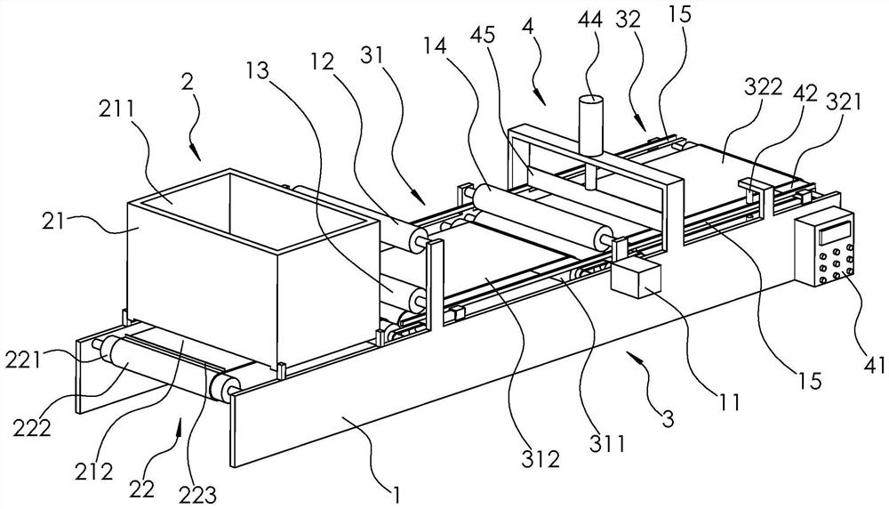
[0032] The following is attached Figure 1-3 The application is described in further detail.

[0033] The embodiment of the present application discloses a printed matter surface coating device. Such as figure 1 As shown, a printed matter surface coating equipment includes a bracket 1 and a motor 11 fixed on the bracket 1. The bracket 1 is rotatably connected with an unwinding roller 12 and a guide roller 13 arranged at intervals up and down, and the two are arranged at intervals up and down. The hot pressing roll 14, the film is wound on the unwinding roll 12, the film on the unwinding roll 12 walks around the guide roll 13 and passes between the two hot pressing rolls 14; the output shaft of the motor 11 is connected to the The pressure roller 14 extends axially and is fixedly connected to the lower heat pressure roller 14 .

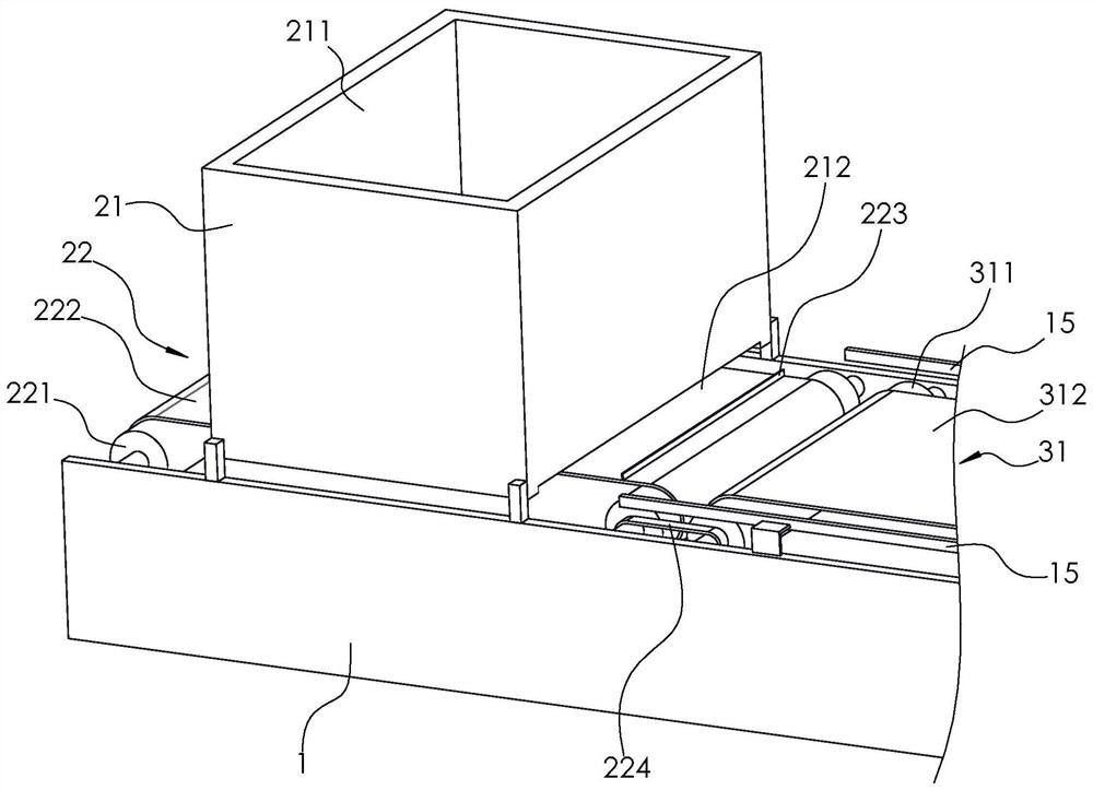
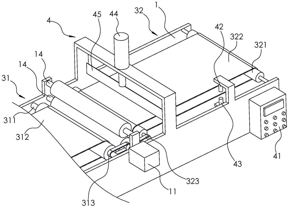
[0034] Such as figure 1 As shown, the support 1 is provided with a feeding mechanism 2, a conveying mechanism 3 and a cutting mechanism 4 arranged...


PUM


Abstract

The invention relates to the technical field of film laminating , in particular to printed matter surface film laminating equipment which comprises a support and a motor arranged on the support. An unwinding roller and two hot-pressing rollers are rotationally connected onto the support; the two hot-pressing rollers are arranged up and down in a spaced mode; an output shaft of the motor is connected to one of the hot-pressing rollers; the support is further provided with a conveying mechanism and a cutting mechanism located between the hot-pressing rollers and the output end of the conveying mechanism; the cutting mechanism comprises a control panel, an infrared transmitter, an infrared receiver and a hydraulic cylinder; the infrared transmitter, the infrared receiver and the hydraulic cylinder are arranged on the support and coupled to the control panel; the infrared transmitter and the infrared receiver are arranged up and down in a spaced mode; a paperboard on the conveying mechanism penetrates through the position between the infrared transmitter and the infrared receiver in a sliding mode; a piston rod of the hydraulic cylinder extends in the vertical direction and is connected with a cutter; the cutter and the infrared transmitter are sequentially arranged in the moving direction of the paperboard; and the horizontal distance between the cutter and the infrared transmitter is equal to the length or the width of the paperboard. According to the printed matter surface film laminating equipment provided by the invention, the film laminating efficiency of the paperboard can be improved.

Description

technical field [0001] The present application relates to the technical field of film covering, in particular to a film covering equipment on the surface of printed matters. Background technique [0002] During the processing of cardboard, it is usually required to be coated. Lamination is to heat-press the transparent plastic film to the surface of the cardboard, so as to protect the cardboard and increase the gloss. [0003] By retrieval, Chinese patent announcement number CN211518495U discloses a UV laminating machine, including a workbench, and both sides of the top of the workbench are welded with a fixed frame, and one side of the fixed frame is provided with a sliding groove, and a sliding block is slidably connected in the sliding groove. Bearings are installed inside the sliding block, and the driving roller is connected to the inside of the workbench through the rotating shaft. The drive motor is installed on one side of the fixed frame through bolts, and the outp...

Claims


Application Information

Patent Timeline
Patent Type & Authority Applications(China)
IPC IPC(8): B41F23/08B32B37/06B32B37/10B32B38/00B29C63/02
CPCB41F23/08B32B37/06B32B37/10B32B38/0004B29C63/0065B29C63/02
Inventor 高宏友张世强倪志划
Owner 杭州美利建印刷有限公司
Learn More