
A turbine-type combined anti-friction tool capable of changing the flow state of drilling fluid

A flow state and drilling fluid technology, which is applied in the directions of liquid/gas jet drilling, earthwork drilling, flushing of boreholes, etc., can solve the problems of low rock-carrying capacity of drilling fluid, unsatisfactory vibration effect, and low drilling efficiency, etc., to achieve The effect of small pressure drop, reduced friction and improved life of drilling tools

Active Publication Date: 2022-02-01
SOUTHWEST PETROLEUM UNIV
View PDF10 Cites 0 Cited by
  • Summary
  • Abstract
  • Description
  • Claims
  • Application Information

AI Technical Summary

Problems solved by technology

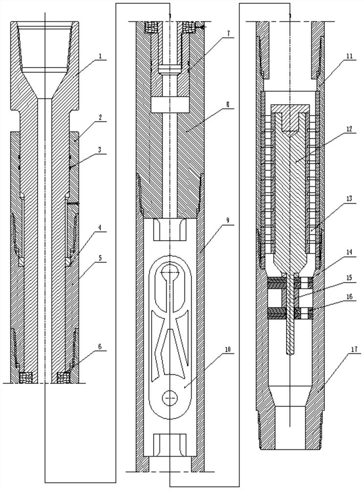
[0004] The purpose of the present invention is: in order to overcome existing unconventional wells such as long horizontal, high-inclination and multi-branch horizontal wells with high drilling friction, resulting in low drilling efficiency, long development cycle, relatively high development cost and the portability of drilling fluid To solve the problems of low rock capacity and unsatisfactory vibration effect, design a turbine-type combined anti-friction tool that can change the flow state of drilling fluid

Method used


Image

  • A turbine-type combined anti-friction tool capable of changing the flow state of drilling fluid
  • A turbine-type combined anti-friction tool capable of changing the flow state of drilling fluid
  • A turbine-type combined anti-friction tool capable of changing the flow state of drilling fluid

Examples


Embodiment Construction

[0014] In order to understand the technical features, objects and effects of the present invention, specific embodiments of the present invention will be described with reference to the drawings.

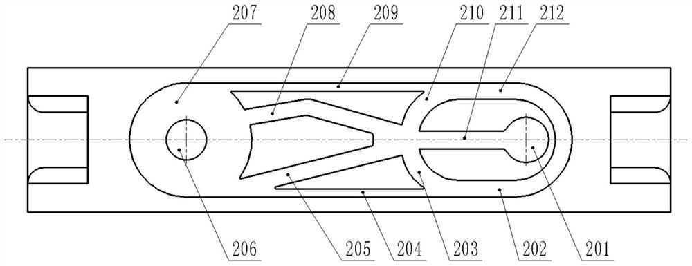
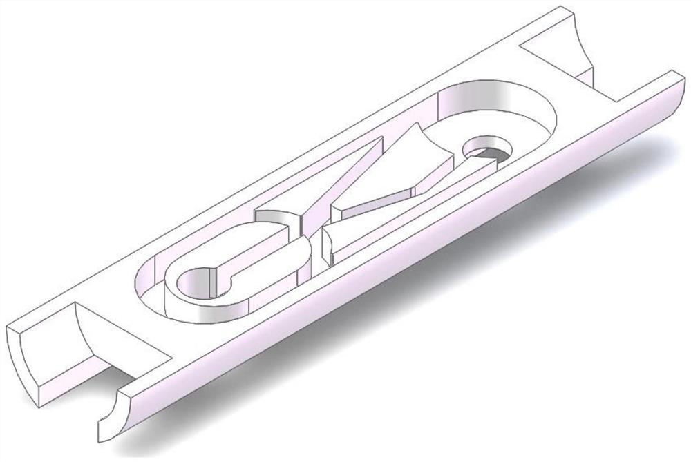
[0015] like Figure 1 - Figure 5 As shown, the turbine combination of the drilling fluid flow state is mainly mainly rod 1, the upper casing A2, the O-shaped seal A3, the limit ring 4, the upper casing B5, the disc spring 6, O-shaped seal B7, housing A8, housing B9, pulse generator 10, lower casing 11, mandrel 12, turbine 13, valve A14, sleeve 15, valve B16, the lower joint 17, the technology is characterized in that the lever 1 Connect to the upper housing B5 by the spline; upper housing A2, the upper casing B5, the outer casing A8, the outer casing B, the lower casing 11, and the lower joint 17 are sequentially connected by the threads; the fluid inlet cone is located in the draw rod 1 inlet At equivalent to a tube, it is used to increase the fluid pressure difference, the improvement ...


PUM


Abstract

The invention is a turbine-type combined anti-friction tool capable of changing the flow state of drilling fluid, which mainly consists of a pull rod, an upper shell A, an O-shaped sealing ring A, a limit ring, an upper shell B, a disc spring, and an O-shaped seal. Ring B, shell A, shell B, pulse generator, lower shell, mandrel, turbine, valve A, sleeve, valve B, and lower joint. Its structural features are: the pull rod is connected to the upper shell B through splines ;The upper casing A, the upper casing B, the casing A, the casing B, the lower casing, and the lower joint are connected to each other through threads in turn; the drilling fluid enters the pulse generator, thereby generating the first pressure pulse; then the drilling fluid drives the turbine Rotate, so as to drive the valve A on the mandrel to rotate, the flow area between valve A and fixed valve B will change, and the second pressure pulse will be generated; the two pressure pulses will be superimposed, causing the pull rod to vibrate axially, and the drill will The static friction between the tool and the well wall is converted into dynamic friction, reducing frictional resistance. The invention can effectively solve the problems of large friction in unconventional drilling.

Description

Technical field [0001] The present invention relates to a turbine combined anti-premises tool that can alter the flow of drilling fluids, a field of oil, natural gas mining drilling tool technology. Background technique [0002] With the continuous mining of oil, the large number of long levels, large slope and multi-branch wells need to be excavated. There are many problems such as toroidal, card diamonds, and drill breaks in China, which lead to a low-efficiency of drilling, and long development cycles, and less development costs. The design requirements of the body trajectory, the target rate in the destination layer, the low-grade capacity of drilling fluids, and the vibration effect is not ideal. This is the main bottleneck that restricts long-term, large slope and multi-branch well development. The cause of these problems is mainly the friction between the drill string and the well wall is larger than the vertical well. During the sliding drilling process, the drill string ...

Claims


Application Information

Patent Timeline
Patent Type & Authority Patents(China)
IPC IPC(8): E21B7/18E21B21/00E21B21/10E21B41/00
CPCE21B7/18E21B21/00E21B21/10E21B41/00
Inventor 石昌帅王澳祝效华
Owner SOUTHWEST PETROLEUM UNIV
Learn More