Transmitting and receiving separated laser radar optical system

A laser radar and optical system technology, applied in radio wave measurement systems, measurement devices, electromagnetic wave re-radiation and other directions, can solve the problems of narrowing the distance between the sending and receiving ends, expanding the scanning angle, and difficulty in installation and adjustment, and achieves the reduction of constraints and elimination of Interference, the effect of facilitating the design and adjustment of the optical path

Active Publication Date: 2021-07-23
58TH RES INST OF CETC
View PDF8 Cites 2 Cited by
  • Summary
  • Abstract
  • Description
  • Claims
  • Application Information

AI Technical Summary

Problems solved by technology

[0004]The receiving and receiving light path of the laser radar can be divided into a separate sending and receiving device and a combined receiving and receiving device. It causes interference and is difficult to install and adjust, and the separation of transceivers can eliminate optical interference in the system. The disadvantage is that there is a short-distance detection blind zone, and it is necessary to reduce the distance between transceivers or expand the scanning angle. For micro-scanning mirrors, the increase in scanning angle will further require finer beam
The best solution to reduce the angle between the micro-scanning mirror and the beam is to project the beam vertically onto the micro-scanning mirror, and use a beam splitting and combining module to adjust the optical path, which in turn will cause light loss

Method used


Image

  • Transmitting and receiving separated laser radar optical system
  • Transmitting and receiving separated laser radar optical system
  • Transmitting and receiving separated laser radar optical system

Examples


Embodiment 1

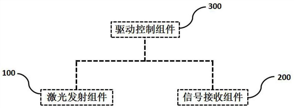
[0031] The present invention provides a laser radar optical system with separate sending and receiving, its structure is as follows figure 1 As shown, the transceiver laser radar optical system includes a laser emitting component 100 , a signal receiving component 200 and a drive control component 300 .

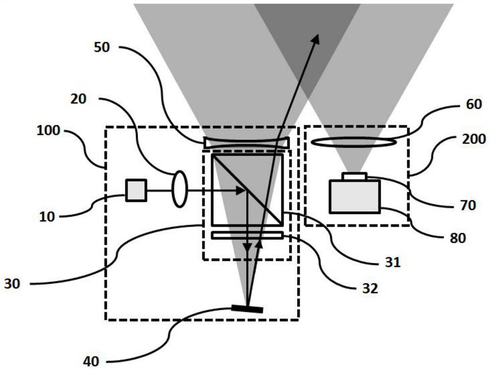
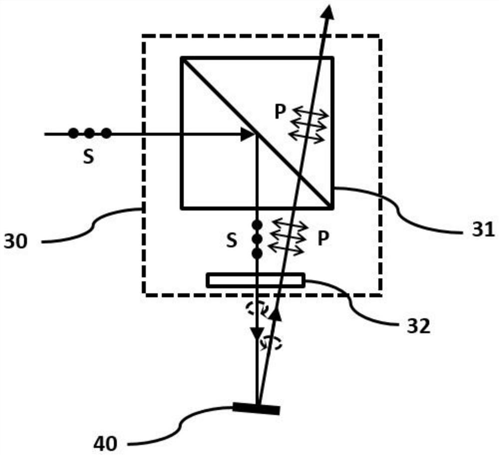
[0032] The laser emitting assembly 100 is used to emit a laser scanning signal to a target object and realize beam scanning; the laser emitting assembly 100 includes a laser light source 10, a beam shaping module 20, a polarization transflective module 30, a projection unit 40 and a field of view expansion unit 50 .

[0033] Such as figure 2 As shown, the laser light source 10 actively emits a laser beam, and the laser beam is shaped and collimated by the beam shaping module 20 to obtain an approximately collimated beam and reduce the divergence angle of the beam so that the laser beam can project a longer distance. Since the beams emitted by the laser light source 10 have...

Embodiment 2

[0044] Such as Figure 4 As shown, an auxiliary system 90 is added on the basis of Example 1, and the auxiliary system 90 includes a polarizing unit 91 and an aperture 92 .

[0045] The polarizing unit 91 is used to polarize the laser beam and optimize the linear polarization of the laser beam. The polarizing unit 91 can be selected but not limited to a linear polarizer; the diaphragm 92 is used to limit the beam. In the beam shaping module 20 pairs of laser beams refine the beam on the basis of shaping and collimation.

[0046] The polarizing unit 91 and the diaphragm 92 are located between the beam shaping module 20 and the polarized transflective module 30, and the area of ​​the polarizing unit 91 needs to be greater than the area of ​​the beam spot passed through; the laser beam passes through the polarizing unit 91 and the light beam. There is no specific requirement on the order of the diaphragms 92 , and the example here is to pass through the polarizing unit 91 first ...


PUM


Abstract

The invention discloses a transmitting and receiving separated laser radar optical system, and belongs to the field of laser radar optics. The laser light source emits laser, the laser is shaped and collimated through the beam shaping module, then reflected to the projection unit through the polarization transmission and reflection module, reflected again and then transmitted through the polarization transmission and reflection module, the scanning angle is increased under the effect of the view field expansion unit, and the laser is emitted to a detection target, and then an echo light signal is reflected, the echo optical signal is projected to a photosensitive surface of the photoelectric detector through the convergence unit and the optical filter and is subjected to photoelectric conversion to generate an electric signal, distance information is calculated through time comparison of subsequent data processing and signal emission, and distance information of a target object in a scanning view field range is obtained by combining a scanning angle of a laser beam. Two-dimensional line scanning detection can be achieved by adopting the one-dimensional scanning micro reflecting mirror, and three-dimensional space detection can be achieved by adopting the two-dimensional scanning micro reflecting mirror.

Description

technical field [0001] The invention relates to the technical field of lidar optics, in particular to a laser radar optical system with separate transceivers. Background technique [0002] Laser radar (LiDAR) is a radar system that uses laser as a carrier to detect long-distance targets and responds to specific information such as target positions through echo signals. Compared with microwave radar, it has the advantages of high resolution, strong anti-interference ability of environmental signals, and small size. It can be widely used in automatic guided vehicles (Automatic Guided Vehicle, AGV), industrial automatic production, unmanned driving, robots and other fields. [0003] The working principle of lidar mainly includes triangulation ranging and time-of-flight ranging (TOF). Among them, the working principle of TOF is to project the laser signal from the internal emission optical system of the lidar to the target object. Back to the collection end of the laser radar, ...

Claims


Application Information

Patent Timeline
Patent Type & Authority Applications(China)
IPC IPC(8): G01S7/481G01S17/08
CPCG01S7/481G01S7/4817G01S17/08
Inventor 魏应强魏敬和刘国柱程进谭叶青
Owner 58TH RES INST OF CETC
Why Eureka
Try Eureka