
Usage equipment based on bioengineering breeding

A bioengineering and equipment technology, applied in the field of bioengineering, can solve problems such as inability to filter impurities, and achieve the effects of improving breeding quality, flexibility and convenience.

Inactive Publication Date: 2021-07-27
包世美
View PDF3 Cites 0 Cited by
  • Summary
  • Abstract
  • Description
  • Claims
  • Application Information

AI Technical Summary

Problems solved by technology

[0005] Aiming at the deficiencies of the prior art, the present invention provides a kind of equipment based on bioengineering breeding, mainly to solve the problem that the breeding screening equipment cannot filter out the impurities in the seeds

Method used


Image

  • Usage equipment based on bioengineering breeding
  • Usage equipment based on bioengineering breeding
  • Usage equipment based on bioengineering breeding

Examples


Embodiment 1

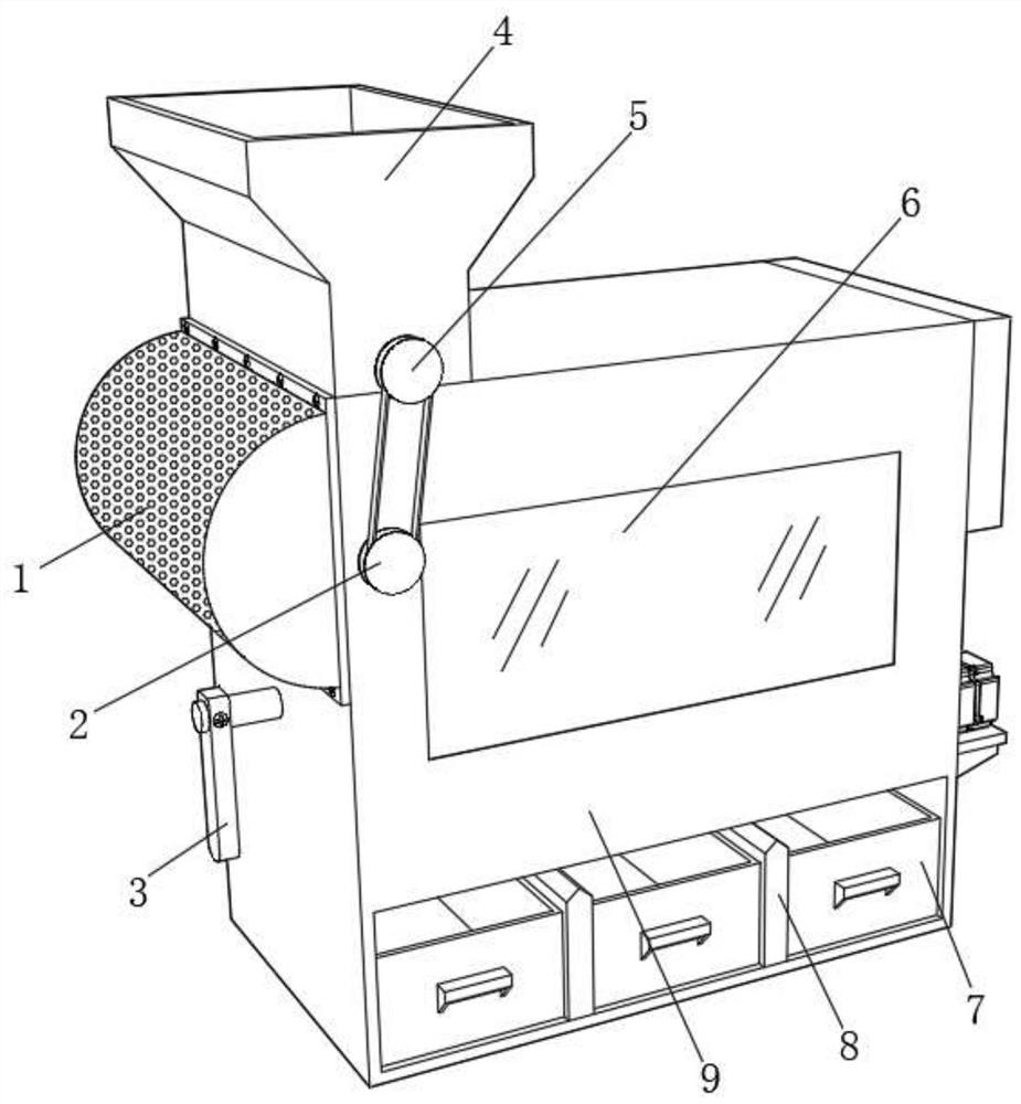
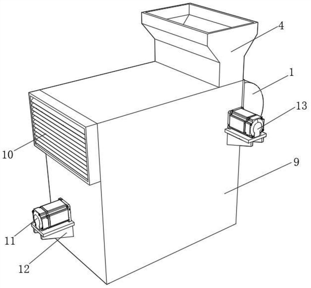
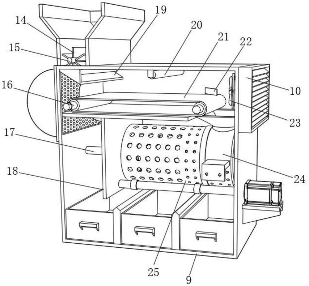
[0034] refer to figure 1 - Fig. 4, a kind of use equipment based on bioengineering breeding, comprises housing 9, and one side of housing 9 is fixed with shield 1 by bolt, and the outer wall of one side of housing 9 is rotatably connected with rotating rod, and one end of rotating rod is fixed by bolt There is a toggle lever 3, and the toggle lever 3 is in contact with the shield 1, the toggle lever 3 on the connecting rod rotates and knocks the shield 1, so that the impurities on the shield 1 can fall downwards, avoiding The baffle 1 is blocked, and the inner wall of one side of the shell 9 is fixed with an exhaust fan 23 by bolts, the inner wall of one side of the shell 9 is fixed with a connecting plate by bolts, and the outer wall of one side of the shell 9 is fixed with a support frame by bolts, and the top of the support frame The surface is fixed with a second motor 13 by bolts, and one side of the casing 9 is rotatably connected with two driving rollers 16, and one sid...

Embodiment 2

[0038] refer to Figure 5 - Fig. 6, a kind of use equipment based on bioengineering breeding, comprises collar 34, and collar 34 is fixed on one side of second dividing plate 18 by bolt, and collar 34 is connected with screen cylinder 25 rotations, and collar 34 One side is provided with a feeding opening, and one side of the feeding opening is fixed with a feeding pipe 35 by bolts, and one side of the screen drum 25 is provided with a feeding hole 33, and the screen drum 25 drives the screw blade 26 to rotate, so that the screw blade 26 will Larger particles of impurities in the material are brought into the discharge hole 33 and discharged to avoid mixing of larger particle impurities with the material. The bottom inner wall of the shell 9 is provided with a second impurity box, and the discharge pipe 35 is located in the second impurity box. Above the box, both sides of the casing 9 are fixed with a second connecting block 36 by bolts, and the second connecting block 36 is ...


PUM


Abstract

The invention relates to the technical field of bioengineering, and discloses usage equipment based on bioengineering breeding. The usage equipment comprises a shell, a blocking cover is fixedly connected to one side of the shell, a rotating rod is movably connected to the outer wall of one side of the shell, a poke rod is fixedly connected to one end of the rotating rod, the poke rod makes contact with the blocking cover, an exhaust fan is fixedly connected to the inner wall of one side of the shell, a connecting plate is fixedly connected to the inner wall of one side of the shell, a supporting frame is fixedly connected to the outer wall of one side of the shell, and a second motor is fixedly connected to the upper surface of the supporting frame. According to the usage equipment, impurities in materials can be blown into the blocking cover through the exhaust fan, so that the breeding quality of the equipment is improved; meanwhile, the discharging speed of a storage hopper can be controlled through fan blades, so that the materials are prevented from being stacked on a conveying belt, and the flexibility of the equipment is improved; large-particle impurities in the materials can be discharged through discharging holes, so that the large particle impurities are prevented from being mixed with the materials.

Description

technical field [0001] The invention relates to the technical field of bioengineering, in particular to a device for breeding based on bioengineering. Background technique [0002] Bioengineering is the combination of various disciplines such as molecular genetics, microbiology, cell biology, biochemistry, chemical engineering and energy science. In the field of new tank technology and environmental protection of new substrates, the cultivation of agriculture benefits from the application of biotechnology, so that high-quality seeds that are more in line with the needs of the people can be screened out. [0003] my country is a large agricultural country, and the cultivation and cultivation of crops is even more important. When breeding, it is necessary to classify and screen the cultivated seeds in large quantities, so as to obtain crop seeds with excellent genes. However, the breeding screening equipment currently on the market cannot filter out the impurities, which will...

Claims


Application Information

Patent Timeline
Patent Type & Authority Applications(China)
IPC IPC(8): B07B4/00B07B1/22B07B1/46B07B9/00B07B11/06B08B15/00A01C1/00
CPCB07B4/00B07B1/22B07B1/46B07B9/00B07B11/06B08B15/00A01C1/00
Inventor 包世美
Owner 包世美
Learn More