Foldable solar cell panel

A technology of solar panels and solar cells, applied in solar thermal power generation, solar thermal energy, solar collectors, etc., can solve problems such as unfavorable service life of cables, low efficiency of absorbing solar energy, accumulation of knotted damage, etc., to achieve convenient removal Effects of dust, improved safety performance, and improved service life

Inactive Publication Date: 2021-07-27
徐美玲
View PDF0 Cites 0 Cited by
  • Summary
  • Abstract
  • Description
  • Claims
  • Application Information

AI Technical Summary

Problems solved by technology

[0002] A solar panel is a device that directly or indirectly converts solar radiation energy into electrical energy through the photoelectric effect or photochemical effect by absorbing sunlight. The main material of most solar panels is "silicon". Compared with ordinary batteries and rechargeable batteries Generally speaking, solar cells are more energy-saving and environmentally friendly green products, so they are widely used. However, when the current solar panels are installed, the shape of the solar panels is fixed and cannot be adjusted, so that the efficiency of absorbing solar energy is low. It cannot be folded, which makes it difficult to carry, and the current solar panels need to transmit electric energy through cables when they are in use, but the cables are often dragged on the ground, causing accumulation, knotting and damage, which is not conducive to the service life of the cables. In view of this, We propose a foldable solar panel

Method used


Image

  • Foldable solar cell panel
  • Foldable solar cell panel
  • Foldable solar cell panel

Examples


Embodiment 1

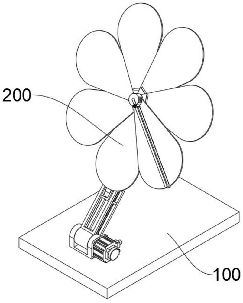
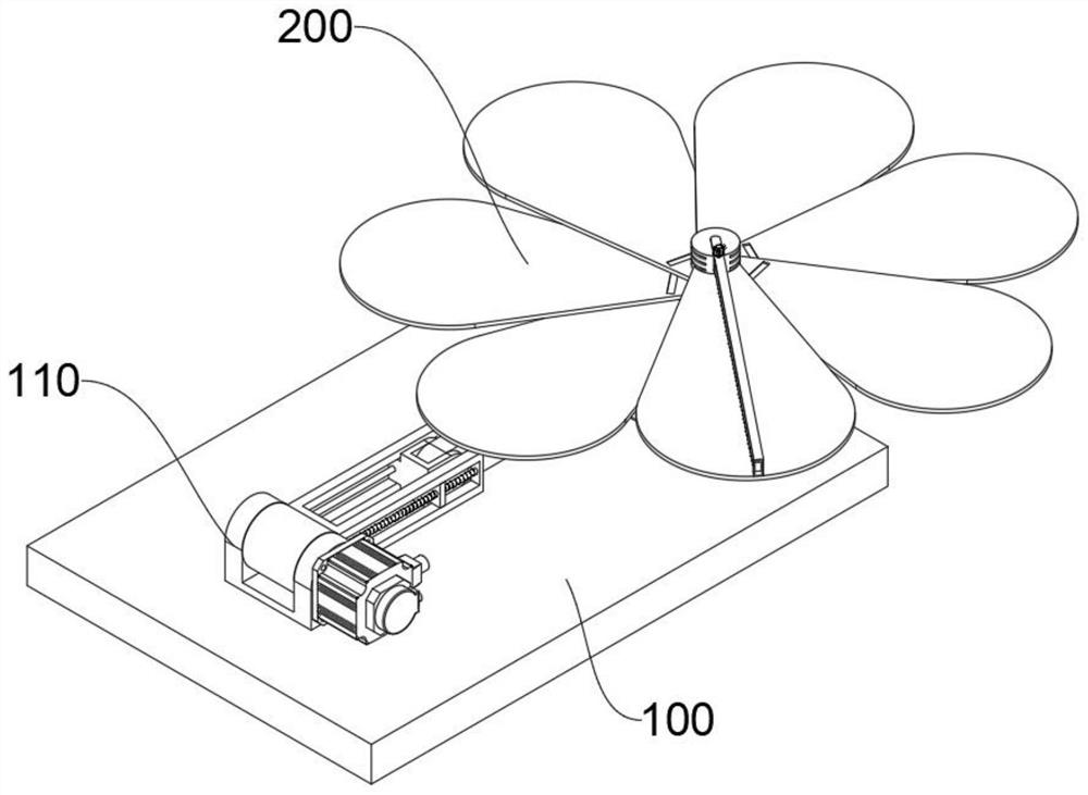
[0042]see Figure 1-Figure 5 As shown, this embodiment provides a foldable solar cell panel, including a mounting plate 100 and a solar cell device 200 above the mounting plate 100, the top of the mounting plate 100 is fixedly connected with a hinged fork 110, and the solar cell device 200 at least includes:

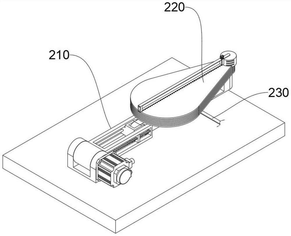
[0043] Folding support mechanism 210, folding support mechanism 210 comprises connection block 211, and connection block 211 rotates inside hinge fork 110, and connection block 211 outer wall is connected with articulation motor 2110 output shaft, and articulation motor 2110 outer wall is fixedly connected to articulation fork 110 outer wall, hinged The motor 2110 is powered on to make it work, and the output shaft of the articulated motor 2110 drives the connecting block 211 to rotate inside the hinged fork 110 to be lighter and easier to operate. There is an adjustment fork 213, and the inner rotation of the adjustment fork 213 is provided with a folding block 214, the...

Embodiment 2

[0048] In order to make the cleaning brush 2219 rotate and brush the tops of the powered solar panels 221 and multiple linkage solar panels 222 in turn, to remove dust and improve the efficiency of light energy absorption, the difference between this embodiment and Embodiment 1 is that, please refer to Figure 6-Figure 7 shown, where:

[0049] The top of the bump 2211 is rotated with a support plate 2214, and the bottom of the support plate 2214 is provided with an adjustment frame 2215 near both ends, and a brush frame 2218 is slid between the adjustment frames 2215, and the brush frame 2218 is "two symmetrical L shape", the bottom of the brush frame 2218 is equidistantly provided with a plurality of cleaning brushes 2219, slide the brush frame 2218 between the two adjustment frames 2215, so that the ends of the cleaning brushes 2219 fit the power solar panel 221, and then brush The plate frame 2218 rotates on the top of the bump 2211 along with the support plate 2214, and at...

Embodiment 3

[0053] In order to facilitate the adjustment of the distance from the connecting rod 215 to the fixed frame 212 and the adjustment of the height of the light energy conversion mechanism 220, the difference between this embodiment and Embodiment 1 is that please refer to Figure 8 shown, where:

[0054] The inner walls of both sides of the fixed frame 212 are provided with moving slots 2120, and the two side walls of the adjustment fork 213 are provided with moving plates 2130. The moving plates 2130 are compatible with the moving slots 2120, and one of the moving slots 2120 is internally rotated with a moving screw rod 2121. , the end of the moving screw 2121 is connected with a moving motor 2122, the moving motor 2122 is embedded in the inner layer of the fixed frame 212, the outer wall of the moving screw 2121 is threadedly connected with the surface of the moving plate 2130, and the moving motor 2122 is powered on to make it work , the output shaft of the mobile motor 2122 ...


PUM


Abstract

The invention relates to the technical field of solar cell panels, in particular to a foldable solar cell panel. The foldable solar cell panel comprises a mounting plate and a solar cell device above the mounting plate, the top of the mounting plate is fixedly connected with a hinge fork, and the solar cell device at least comprises a folding supporting mechanism. The folding supporting mechanism comprises a connecting block, the connecting block is rotatably arranged in the hinge fork, and the end of the connecting block is fixedly connected with a fixing frame. An adjusting fork is slidably arranged in the fixing frame, a folding block is rotationally arranged in the adjusting fork, and a connecting rod and a light energy conversion mechanism are fixedly connected to the end of the folding block. The light energy conversion mechanism comprises a power solar panel, a protruding block is arranged at the end of the power solar panel, and a plurality of linkage solar panels are rotationally laminated at the bottom of the power solar panel. Thefoldable solar cell panel of the present invention is convenient to adjust the angle for absorbing the sunlight, and the foldable solar cell panel can be folded when being not used, and can conveniently winding and arranging cables.

Description

technical field [0001] The invention relates to the technical field of solar battery panels, in particular to a foldable solar battery panel. Background technique [0002] A solar panel is a device that directly or indirectly converts solar radiation energy into electrical energy through the photoelectric effect or photochemical effect by absorbing sunlight. The main material of most solar panels is "silicon". Compared with ordinary batteries and rechargeable batteries Generally speaking, solar cells are more energy-saving and environmentally friendly green products, so they are widely used. However, when the current solar panels are installed, the shape of the solar panels is fixed and cannot be adjusted, so that the efficiency of absorbing solar energy is low. It cannot be folded, which makes it difficult to carry, and the current solar panels need to transmit electric energy through cables when they are in use, but the cables are often dragged on the ground, causing accum...

Claims


Application Information

Patent Timeline
Patent Type & Authority Applications(China)
IPC IPC(8): H02S20/30H02S30/20H02S40/10F24S30/425B65H75/44
CPCB65H75/4481B65H2701/34F24S30/425H02S20/30H02S30/20H02S40/10Y02E10/47Y02E10/50
Inventor 徐美玲周乃琴
Owner 徐美玲
Why Eureka
Try Eureka