Waste lithium ion power battery pack shell cutting system

A power battery pack and cutting system technology, applied in secondary batteries, battery recycling, circuits, etc., can solve problems such as potential safety hazards, inability to cool down the cutting disc, and affecting the service life of the cutting disc, so as to improve the service life and increase the cooling speed effect

Active Publication Date: 2021-07-30
JINAN G WEIKE SCI & TECH
View PDF7 Cites 1 Cited by
  • Summary
  • Abstract
  • Description
  • Claims
  • Application Information

AI Technical Summary

Problems solved by technology

[0004] The purpose of the present invention is to solve the problem that the cutting device for the casing of the waste lithium-ion power battery pack in the prior art cannot timely cool down the high-temperature cutting disk, which will easily affect the service life of the cutting disk and cause potential safety hazards at the same time. A cutting system for shells of waste lithium-ion power battery packs

Method used


Image

  • Waste lithium ion power battery pack shell cutting system
  • Waste lithium ion power battery pack shell cutting system
  • Waste lithium ion power battery pack shell cutting system

Examples


Embodiment 1

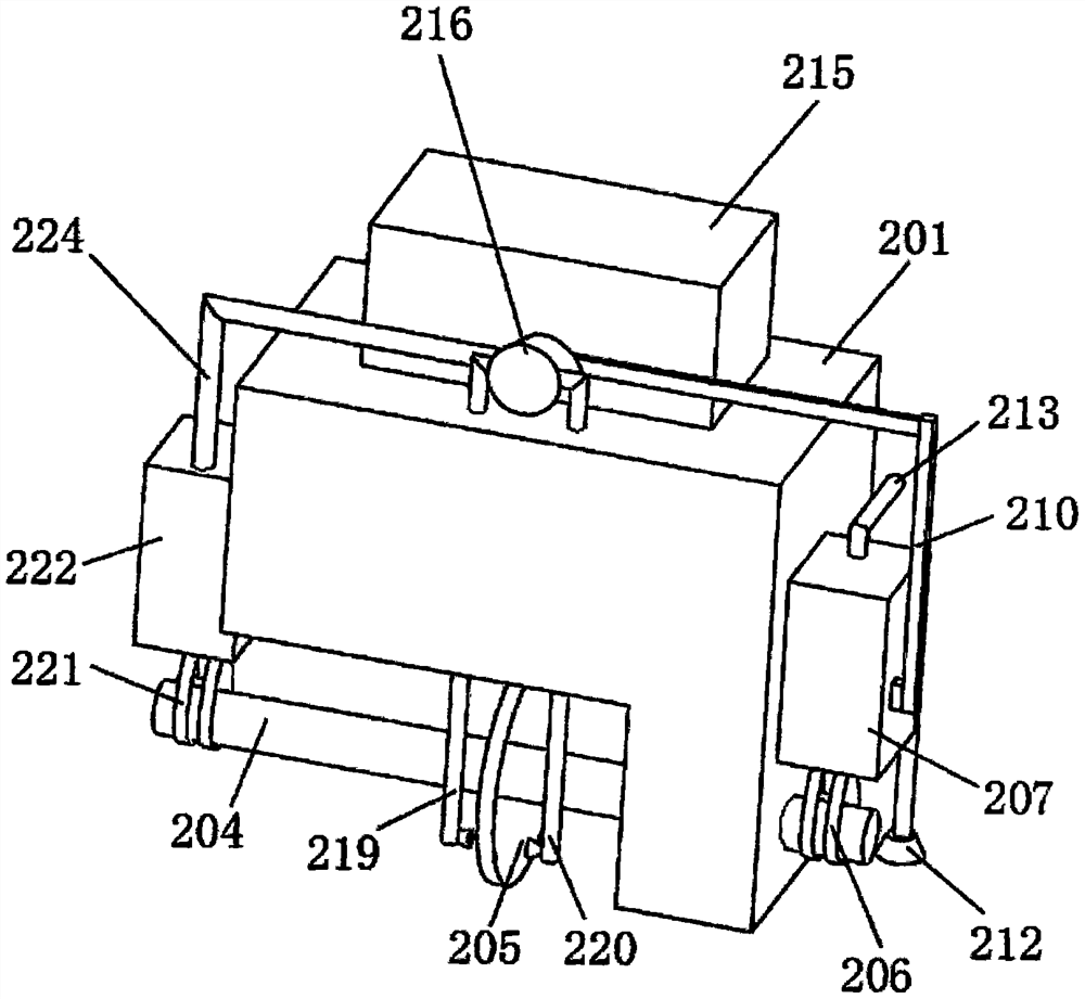
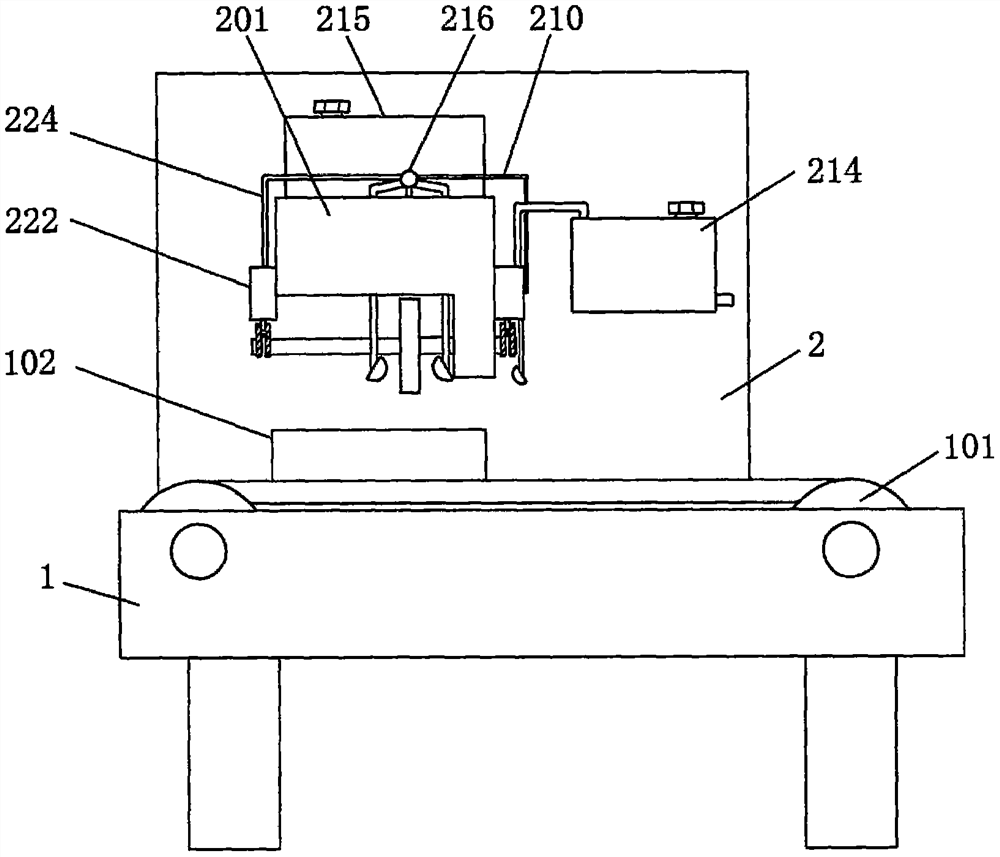
[0032] refer to Figure 1-7 , a waste lithium-ion power battery case cutting system, including a workbench 1, a conveyor belt 101 and a battery pack body 102, the conveyor belt 101 is set on the workbench 1, the battery pack body 102 is placed on the conveyor belt 101, and also includes: a riser 2. It is fixedly connected to the workbench 1; the connecting shell 201 is fixedly connected to the side wall of the riser 2; the cutting mechanism is set in the connecting shell 201 for cutting the battery pack body 102; the cooling mechanism is set in the connecting shell 201 on, used to cool down the cutting device; the heat conduction mechanism is arranged on the connecting shell 201, and is used to conduct the heat generated by cutting to the cooling mechanism; the motor 202 is fixedly connected in the connecting shell 201; it is used to drive the cutting mechanism, cool down Mechanism and heat conduction mechanism work.

[0033] When performing cutting work, the battery pack bod...

Embodiment 2

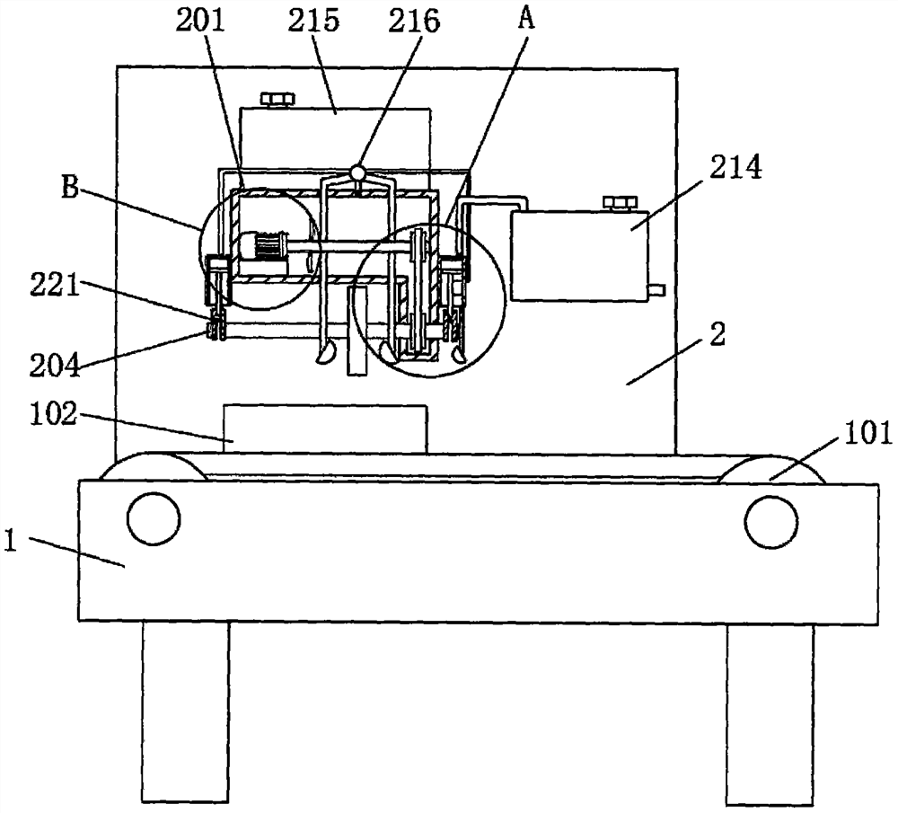
[0035] refer to figure 1 , figure 2 , image 3 , Figure 4 , Figure 5 and Figure 7, is basically the same as Embodiment 1, furthermore, in order to cut the battery pack body 102, the cutting mechanism includes a first heat conducting rod 204 and a cutting disc 205, the output end of the motor 202 is fixedly connected with a rotating shaft 203, and the first heat conducting rod 204 Rotationally connected to the bottom of the connecting shell 201, the first pulley is connected on the rotating shaft 203, the second pulley matched with the first pulley is connected on the first heat conducting rod 204, the first pulley and the second pulley A belt is connected, and the cutting disc 205 is fixedly connected to the first heat conducting rod 204 .

[0036] When cutting, turn on the motor 202, and the rotating shaft 203 on the output end of the motor 202 drives the second pulley to rotate through the first pulley, thereby driving the first heat conducting rod 204 to rotate, an...

Embodiment 3

[0038] refer to figure 1 , figure 2 , image 3 , Figure 4 , Figure 5 and Figure 7 , is basically the same as Embodiment 1, furthermore, in order to transfer the heat generated by cutting to the cooling mechanism, the heat conduction mechanism includes a first crankshaft 206, a first connection box 207, a heat conduction plate 209 and a second heat conduction rod 210, the first The crankshaft 206 is fixedly connected to the first heat conducting rod 204, the first connection box 207 is fixedly connected to the side wall of the connection shell 201, and the outer wall of the first crankshaft 206 is rotatably connected to the first connecting rod 208, which is far away from the first connecting rod 208. One end of a crankshaft 206 is connected in the first connection box 207, the heat conduction plate 209 is fixedly connected in the first connection box 207, the outer wall of the first connection rod 208 is attached to the outer wall of the heat conduction plate 209, and ...


PUM


Abstract

The invention discloses a waste lithium ion power battery pack shell cutting system, and belongs to the technical field of waste lithium ion power battery pack treatment. The waste lithium ion power battery pack shell cutting system includes a workbench, a conveying belt and a battery pack body, wherein the conveying belt is arranged on the workbench, and the battery pack body is placed on the conveying belt. The waste lithium ion power battery pack shell cutting system further includes a vertical plate fixedly connected to the workbench; a connecting shell fixedly connected to a side wall of the vertical plate; a cutting mechanism arranged in the connecting shell and used for cutting the battery pack body; a cooling mechanism arranged on the connecting shell and used for cooling a cutting device; a heat conduction mechanism arranged on the connecting shell and used for conducting heat generated by cutting to the cooling mechanism; and a motor fixedly connected to the inside of the connecting shell. According to the present invention, automatic and rapid cooling can be conducted in a cutting process according to the temperature of a cutting disc, so that the service life of the cutting disc is prolonged.

Description

technical field [0001] The invention relates to the technical field of processing waste lithium ion power battery packs, in particular to a cutting system for shells of waste lithium ion power battery packs. Background technique [0002] Lithium-ion power battery is a new type of high-energy battery successfully developed in the 20th century. The negative electrode of this battery is graphite and other materials, and the positive electrode is lithium iron phosphate, lithium cobaltate, lithium titanate, etc., and because of its high energy, high battery voltage, The advantages of wide working temperature range and long storage life have been widely used in military and civilian small electrical appliances. When lithium-ion power battery packs are used for a long time, users usually scrap them. However, lithium-ion power battery packs Scrapping may not be carried out immediately after recycling, but cascade utilization can also be carried out. The so-called cascade utilization...

Claims


Application Information

Patent Timeline
Patent Type & Authority Applications(China)
IPC IPC(8): B23D19/00B23D33/00B23Q11/00B23Q11/10H01M10/0525H01M10/54
CPCB23D19/00B23D33/00B23Q11/10B23Q11/0046B23Q11/00H01M10/54H01M10/0525Y02W30/84Y02E60/10
Inventor 蒋习锋李健
Owner JINAN G WEIKE SCI & TECH
Why Eureka
Try Eureka