Laser welding workstation for turbine hardware
A laser welding and hardware technology, which is applied in laser welding equipment, welding equipment, metal processing equipment, etc., can solve the problems of welding slag splashing, decreased welding efficiency of turbine hardware, poor continuity of welding process, etc.
- Summary
- Abstract
- Description
- Claims
- Application Information
AI Technical Summary
Problems solved by technology
Method used
Image

Examples
Embodiment 1
[0036] According to an embodiment of the present invention,
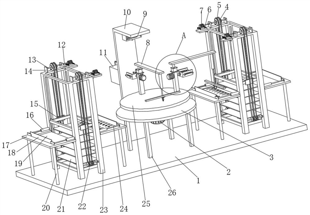
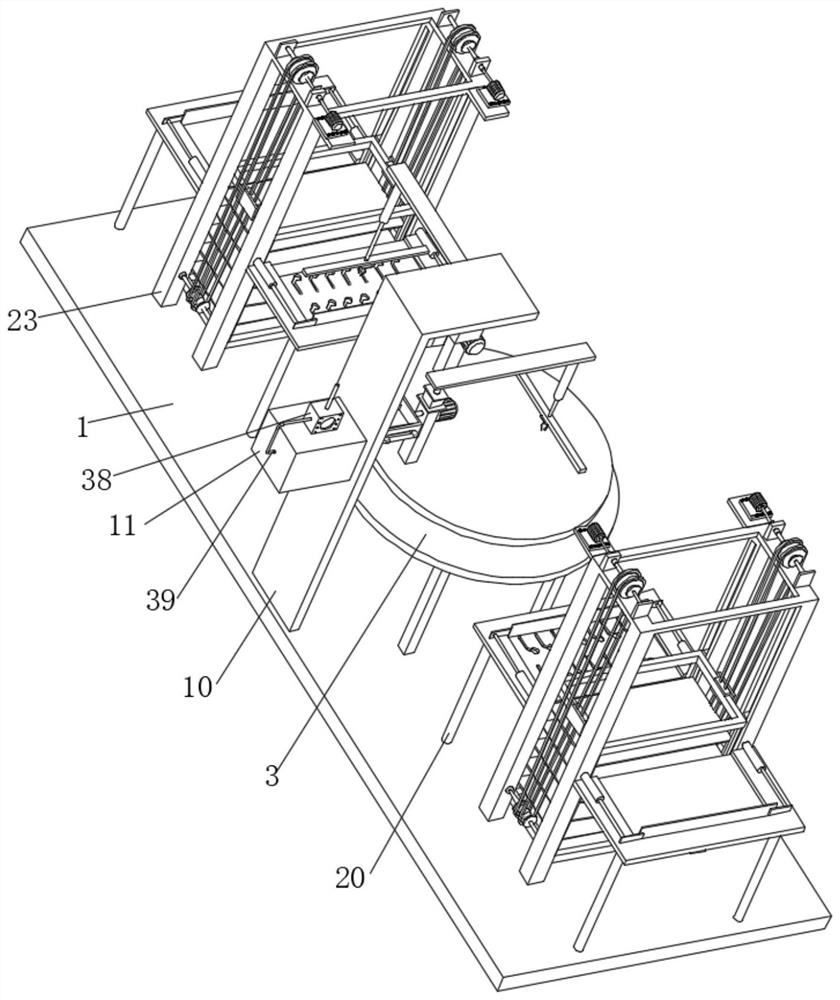
[0037] see Figure 1-6 , turbine hardware laser welding workstation, 1. Including table body 1, blister tray 24, mounting frame 10, feeding structure, grabbing structure, clamping structure, welding structure, dust removal structure, the top of table body 1 is fixedly connected with The support leg 26, the end of the support leg 26 away from the table body 1 is fixedly connected with the fixed plate 3, the bottom of the fixed plate 3 is fixedly connected with the first motor 2, and the output shaft end of the first motor 2 is fixedly connected with the rotary table 25, which is plastic-absorbed The bottom of the tray 24 is provided with placement grooves distributed equidistantly, and hardware bodies are placed in the placement grooves;
[0038] The feeding structure is arranged on the top of the bottom plate 1 for fast loading and unloading of the blister tray 24;
[0039] The grasping structure is arranged on th...
Embodiment 2
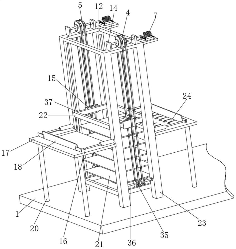
[0044] see Figure 1-3 , the feeding assembly includes a support frame 23 fixedly connected to the top of the bottom plate 1, the top of the support frame 23 is fixedly connected to the mounting base 6, the top of the mounting base 6 is fixedly connected to the second motor 7, and one end of the output shaft of the second motor 7 is fixed Connected with the first rotating rod 13, the top of the support frame 23 is fixedly connected with the supporting plate 14, forming a rotating connection between one end of the first rotating rod 13 and the supporting plate 14, and the peripheral outer wall of the first rotating rod 13 is fixedly connected with the first Transmission wheel 4, the circumference outer wall transmission of the first transmission wheel 4 is connected with transmission belt 5, and one side of transmission belt 5 is fixedly connected with fixed plate 15, and the side of fixed plate 15 away from transmission belt 5 is fixedly connected with fixed frame 22, fixed Bo...
Embodiment 3
[0046] see figure 1 , 2 5. The grasping structure includes a vertical bar 33 fixedly connected to the top of the turntable 25, the top of the vertical bar 33 is fixedly connected with a third motor 27, and one end of the output shaft of the third motor 27 is fixedly connected with the first connecting plate 8, the second The bottom of a connection plate 8 is provided with a first groove 40, the inside of the first groove 40 is fixedly connected with a first electric slide rail, and the inner walls of both sides of the first electric slide rail are slidably connected with a first electric slider 41. The bottom of an electric slider 41 is fixedly connected with a second electric push rod 42, and one end of the second electric push rod 42 away from the first electric slider 41 is fixedly connected with a second connecting plate 48, and the bottom of the second connecting plate 48 is provided with The second groove 45, the inner wall of one side of the second groove 45 is fixedly...
PUM
 Abstract
Description
Claims
Application Information
 - R&D
- Intellectual Property
- Life Sciences
- Materials
- Tech Scout
- Unparalleled Data Quality
- Higher Quality Content
- 60% Fewer Hallucinations
Browse by: Latest US Patents, China's latest patents, Technical Efficacy Thesaurus, Application Domain, Technology Topic, Popular Technical Reports.
© 2025 PatSnap. All rights reserved.Legal|Privacy policy|Modern Slavery Act Transparency Statement|Sitemap|About US| Contact US: help@patsnap.com