Supercharge Your Innovation With Domain-Expert AI Agents!

Laser marking device and laser marking method for flame-retardant cable

A laser marking and cable technology, applied in the field of laser marking, can solve the problems of destroying the flame retardancy of flame-retardant cables, unenvironmental protection of coding, poor adhesion, etc., and achieve full life cycle traceability and color contrast threshold Enhanced and fast warehousing effect

Pending Publication Date: 2021-08-03
SHANDONG LASER TECH
View PDF11 Cites 1 Cited by
  • Summary
  • Abstract
  • Description
  • Claims
  • Application Information

AI Technical Summary

Problems solved by technology

[0003] The purpose of the present invention is to provide a flame-retardant cable laser marking device, which can keep the flame-retardant cable surface after coding with the original flame retardancy, and has no peculiar smell and smoke, and solves the problem of flame-retardant cable laser marking. The existence of marking codes destroys the flame retardancy of flame-retardant cables and a large amount of smoke and ink printing is not environmentally friendly, pollutes, and has poor adhesion

Method used


Image

  • Laser marking device and laser marking method for flame-retardant cable
  • Laser marking device and laser marking method for flame-retardant cable
  • Laser marking device and laser marking method for flame-retardant cable

Examples


Embodiment 1

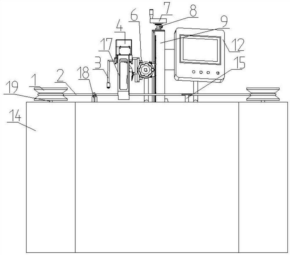
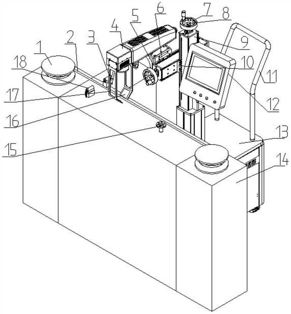
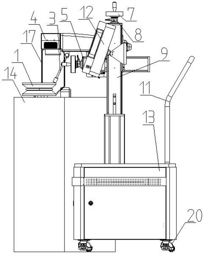
[0024] Example 1, such as Figures 1 to 5 As shown, the present invention is a flame-retardant cable laser marking device, including a workbench 14, on which a conveying device for conveying a flame-retardant cable 2 containing laser laser powder in the cable sheath is installed, and the flame-retardant The top of the cable 2 is provided with a marking head 4, and the front and rear sides of the flame-retardant cable 2 are provided with reflectors 16 inclined at 45 degrees to the horizontal plane. The reflector 16 is installed at the bottom of the marking head 4, and the marking head 4 is connected There are front and rear adjustment devices, the front and rear adjustment devices are connected with up and down adjustment devices, and the bottom of the up and down adjustment devices is fixed on the fiber laser marking machine cabinet 13.

[0025] The front end of marking head 4 is fixed with two mounting frames 17, and the bottom of mounting frame 17 is turned inwardly, and the...

Embodiment 2

[0039] Embodiment 2 is a laser marking method for a flame-retardant cable, which includes the following steps, S1, uniformly adding laser laser powder when the flame-retardant cable 2 is formed, S2, placing the flame-retardant cable 2 on the conveying device, and then The marking head 4 of the fiber laser marking device emits laser light, and the laser beam is emitted to the double-sided mirror 16, and the laser reflected by the mirror 16 performs laser marking on both sides of the flame-retardant cable, and the laser marking of the flame-retardant cable The laser laser powder in the area quickly absorbs the laser, and there is a color difference with the original material. Laser marking is realized on the flame-retardant cable. S3, the marked flame-retardant cable is rolled up and put into storage.

[0040] In step S1, the laser laser powder accounts for 0.1%-0.2% of the total weight of the total flame-retardant cable coating, and the fiber laser marking device in the step S2 ...


PUM


Abstract

The invention relates to a laser marking device and laser marking method for a flame-retardant cable. The laser marking device comprises a workbench, wherein a conveying device for conveying a flame-retardant cable with a cable cladding containing laser powder is installed on the workbench; a marking head is arranged at the top of the flame-retardant cable; reflectors which incline 45 degrees relative to the horizontal plane are arranged at the front side and the rear side of the flame-retardant cable, and the reflectors are installed at the lower part of the marking head; the marking head is connected with a front-back adjusting device; the front-back adjusting device is connected with an up-down adjusting device; and the bottom of the up-down adjusting device is fixed to an optical fiber laser marking machine cabinet. According to the laser marking device and the laser marking method, a flame-retardant cable code does not generate other harmful substances, only the laser powder added into the flame-retardant cable cladding is used for rapid marking and color changing, smoke or peculiar smell is avoided, the laser-marked flame-retardant cable code has the indelible characteristic, under reflection of the double-faced reflectors, rapid and convenient marking is carried out on two sides of a cylindrical cable, and the problem that specific coding information cannot be inquired due to the fact that one side of the cable is shielded after use is avoided.

Description

technical field [0001] The invention belongs to the technical field of laser marking, and in particular relates to a flame-retardant cable laser marking device and a marking method thereof. Background technique [0002] In the field of industrial consumer goods, flame-retardant cable marking methods are mostly inkjet coding or UV laser marking. When inkjet coding is used, ink is used as the main consumable, and the usage is large. The ink is sensitive to temperature changes and when the air humidity is not constant. The nozzles of inkjet printers are prone to blockage, leakage, dripping, popping, etc., and produce sewage discharge, and the adhesion of inkjet codes is poor, which cannot meet the conditions of long-term traceability; when marking with 266nm-355nm ultraviolet lasers, due to the The wavelength of the laser is short, which directly destroys the molecular structure of the material, changes the properties of the material surface, and has a strong marking color cont...

Claims


Application Information

Patent Timeline
IPC IPC(8): B23K26/362B23K26/70
CPCB23K26/362B23K26/702
Inventor 车轶赵金阳司川岳
Owner SHANDONG LASER TECH
Features
  • R&D
  • Intellectual Property
  • Life Sciences
  • Materials
  • Tech Scout
  • Unparalleled Data Quality
  • Higher Quality Content
  • 60% Fewer Hallucinations
Learn More