An underground automatic adjustable safety protection vehicle and its use method
An adjustable and protective car technology, which is applied in the directions of safety devices, earthwork drilling, underground transportation, etc., can solve the problems that the protective devices cannot move freely, the high cost of the device, and the poor ability to adapt to the environment, so as to save time, cost and Effects of labor costs, maintaining balance, and reducing workload
- Summary
- Abstract
- Description
- Claims
- Application Information
AI Technical Summary
Problems solved by technology
Method used
Image
Examples
Embodiment 1
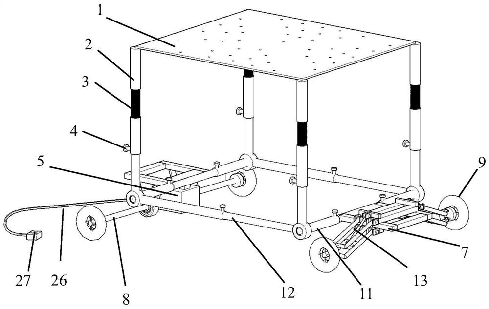
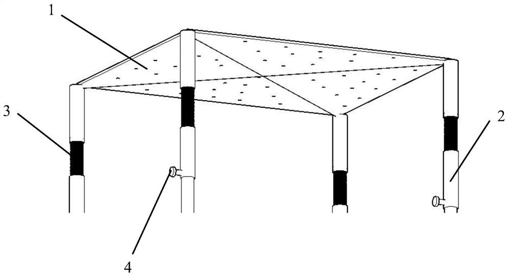
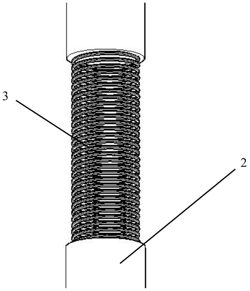
[0039] see Figure 1-7 , a kind of underground automatic adjustable safety protection vehicle provided by this example, including adjustable height strut 2, adjustable length cross bar 12, shock absorber 3, flexible protective ceiling 1, power unit 5, wheels 9, rear wheel buffer Device 6, power connecting rod 8, U-shaped steel frame 7, U-shaped steel frame fixed rod 11, hydraulic vehicle frame, threaded knob 4, wire 26, controller 27 and power device fixed body 28, wherein, the adjustable The length cross bar 12 and the U-shaped steel frame fixing bar 11 arranged opposite to each other constitute the chassis skeleton structure of the protective vehicle, the adjustable height strut 2 is installed on the chassis skeleton structure, and the flexible protective ceiling 1 is fixed on the upper end of the adjustable height strut 2 The U-shaped steel frame 7 is fixed on the U-shaped steel frame fixing rod 11, and the rear wheel buffer 6 is fixed on the lower end of one side of the U-...
Embodiment 2
[0047] This embodiment provides a method for using the underground automatic adjustable safety protection vehicle in Embodiment 1, which is characterized in that it includes the following steps:
[0048] Step 1: Select a suitable location for the roadway that needs to be drilled and excavated underground, prepare the rod material of the protective device, and prepare for assembly;
[0049] Step 2: Install the power connecting rod 8 on the power device 5, then install the two rear wheel buffers 6 into the power connecting rod through the bearing 10, and fix the rear wheel buffers on the U-shaped steel frame through nuts, Install the wheels on both ends of the power connecting rod;
[0050] Step 3: Install two adjustable length crossbars to both ends of the two U-shaped steel frame fixing rods in turn, making them connect the hydraulic frame at the front wheel and the power unit structure of the rear wheel as connecting rods, and it is completed Assembly of the frame structure ...
PUM
 Abstract
Description
Claims
Application Information
 - R&D
- Intellectual Property
- Life Sciences
- Materials
- Tech Scout
- Unparalleled Data Quality
- Higher Quality Content
- 60% Fewer Hallucinations
Browse by: Latest US Patents, China's latest patents, Technical Efficacy Thesaurus, Application Domain, Technology Topic, Popular Technical Reports.
© 2025 PatSnap. All rights reserved.Legal|Privacy policy|Modern Slavery Act Transparency Statement|Sitemap|About US| Contact US: help@patsnap.com


