
Belt type sintering machine protection device capable of continuously working

A belt-type sintering machine and protective device technology, applied in descaling devices, furnaces, charge control and other directions, can solve the problems of easily hitting the sintering port of the sintering machine, the influence of the surface of the trolley, and the cracking of ore, so as to avoid uneven heating. , to ensure rapid recovery and avoid the effect of bursting

Active Publication Date: 2021-08-03
河北新金钢铁有限公司
View PDF6 Cites 0 Cited by
  • Summary
  • Abstract
  • Description
  • Claims
  • Application Information

AI Technical Summary

Problems solved by technology

[0004] The present invention provides a belt-type sintering machine protection device that can work continuously, which can effectively solve the problems raised in the background technology mentioned above. At present, during sintering, materials are piled up on the moving frame due to excessive feeding speed, and the moving frame drives the material. When moving, it will hit the trolley, which will affect the surface of the trolley. At the same time, some oversized ore will be stuck at the position of the feeding port of the trolley, which will affect the subsequent feeding. The mobile frame and ore are not preheated. As a result, the ore bursts when the temperature rises rapidly, and it is easy to hit the sintering port of the sintering machine

Method used


Image

  • Belt type sintering machine protection device capable of continuously working
  • Belt type sintering machine protection device capable of continuously working
  • Belt type sintering machine protection device capable of continuously working

Examples


Embodiment Construction

[0034] The preferred embodiments of the present invention will be described below with reference to the accompanying drawings. It should be understood that the preferred embodiments described herein are only used to illustrate and explain the present invention, but not to limit the present invention.

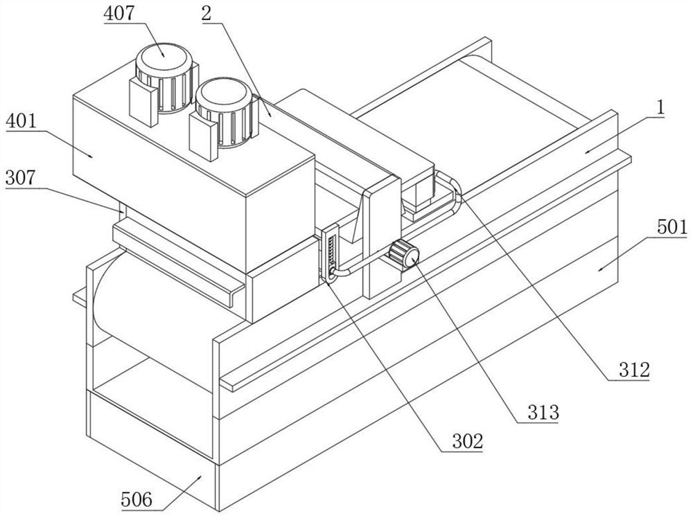
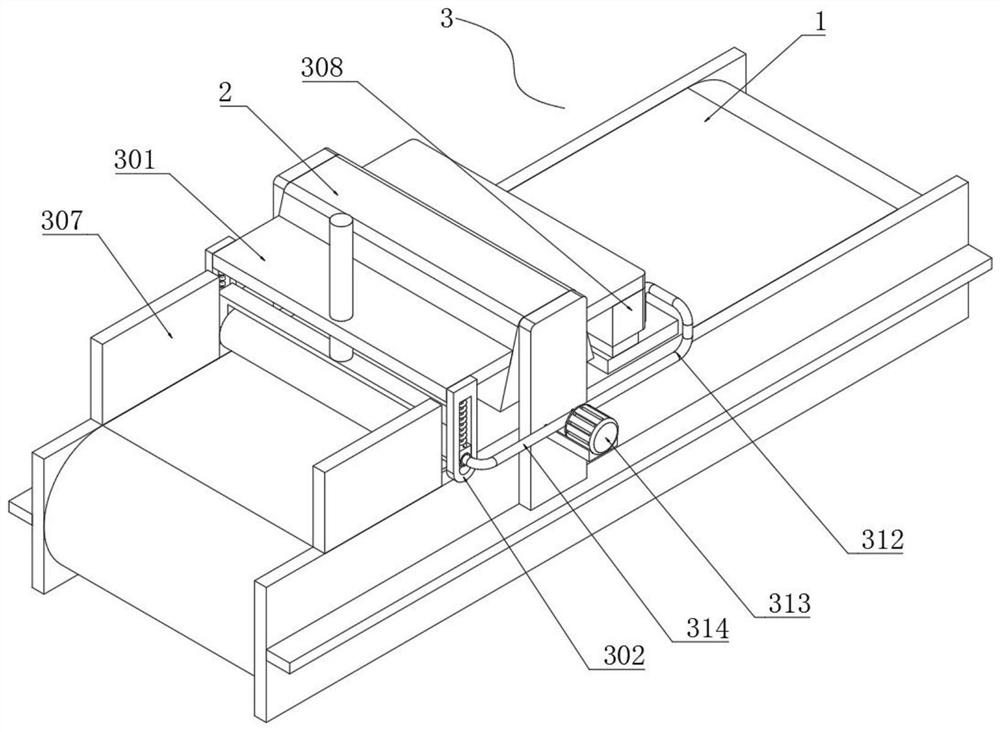
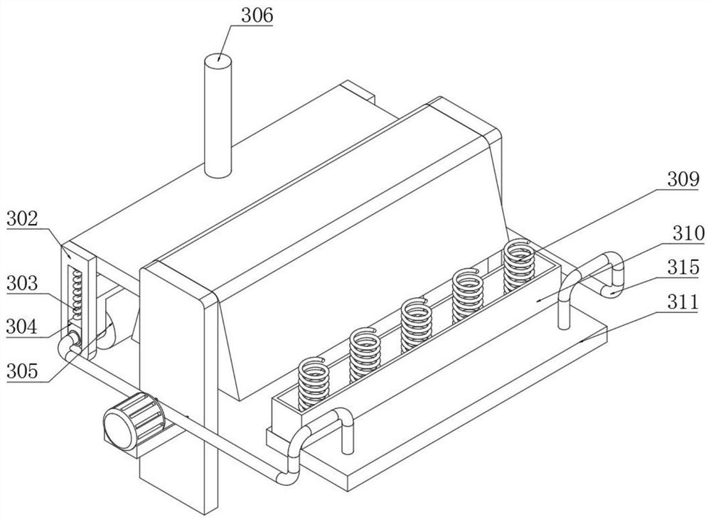
[0035] Example: as Figure 1-6 As shown, the present invention provides a technical solution, a belt-type sintering machine protection device that can work continuously, including a mobile frame 1, a trolley 2 is installed on one side of the top of the movable frame 1, and a protection component is installed on one side of the trolley 2 3. The protection assembly 3 includes a fixed support plate 301, an inner hole limiting plate 302, a lower pressure spring 303, an inner ring limit frame 304, a lower pressure heat conduction cylinder 305, a lower pressure hydraulic cylinder 306, a limit protection plate 307, and a fixed support box. 308, limit spring 309, fixed connection box 31...


PUM


Abstract

The invention discloses a belt type sintering machine protection device capable of continuously working, the bottom end of a pressing spring is in spot welding connection with an inner ring limiting frame, the side end of the inner ring limiting frame is rotationally connected with a pressing heat conduction cylinder, a limiting spring is welded at the bottom end of a fixed supporting box, and a heat conduction circulating box is welded at the bottom end of a fixed connecting box. A water outlet pipe penetrates through one side of the top end of the heat conduction circulating box, a backflow pipe penetrates through one end of the pressing heat conduction cylinder, the height of materials is limited through the pressing heat conduction cylinder and a limiting protection plate, meanwhile, a large number of materials are prevented from being stacked together, therefore the materials are prevented from colliding with a trolley in the conveying process, a heated effect of the materials can be guaranteed by flatly laying the materials, then the sintered materials are rapidly cooled through the heat conduction circulating box, heat obtained after heat dissipation flows into the pressing heat conduction cylinder, therefore the unsintered materials are preheated, and the situation that the materials are burst out due to the fact that the heating speed of the materials is too high is avoided.

Description

technical field [0001] The invention relates to the technical field of sintering, in particular to a belt-type sintering machine protection device that can work continuously. Background technique [0002] As one of the blast furnace raw material supply equipment, the sintering machine plays a very important role. The sintering machine trolley is mainly responsible for charging, igniting, sintering on the track and discharging the sinter at the tail. The belt sintering machine is the main equipment in the sintering process. , The tail execution traction mechanism is mainly composed of a trolley, a roller, a tail star wheel, a tail track, a counterweight, and a moving frame. [0003] However, at present, during sintering, the material will accumulate on the moving frame due to the excessive cutting speed. When the moving frame drives the material to move, it will hit the trolley, which will affect the surface of the trolley. At the same time, some large ore It will be stuck a...

Claims


Application Information

Patent Timeline
Patent Type & Authority Applications(China)
IPC IPC(8): F27D3/12F27D25/00
CPCF27D3/12F27D25/001
Inventor 李兆甲张军慧朱晓旭张艮涛任海义
Owner 河北新金钢铁有限公司
Learn More