
Thermal battery cable connection structure used in environment of 450 DEG C

A connection structure, thermal battery technology, applied in the direction of structural parts, insulated cables, battery pack components, etc., can solve problems such as falling off, loose cables and terminals, thermal battery can not be reliable power, etc., to achieve the integrity of the insulation layer, connection firm effect

Pending Publication Date: 2021-08-03
SHANGHAI INST OF SPACE POWER SOURCES
View PDF4 Cites 0 Cited by
  • Summary
  • Abstract
  • Description
  • Claims
  • Application Information

AI Technical Summary

Problems solved by technology

At present, the melting temperature of tin-lead solder is between 180°C and 320°C. When the operating temperature of the thermal battery reaches 450°C, the tin-lead solder will melt and flow. On the one hand, the molten solder makes the positive and negative electrodes, the positive and negative electrodes and the There is a hidden danger of short circuit between the battery shells, which reduces the safety performance of the thermal battery; on the other hand, after the soldering is melted, it may cause the cable and the terminal to loosen and fall off, resulting in the thermal battery not being able to output power reliably.
[0004] The temperature resistance of power output cables usually used by thermal batteries is below 250°C, which cannot meet the needs of the working environment temperature of 450°C. In order to ensure the reliable operation of thermal batteries in high temperature environments, the connection structure of thermal battery cables must be improved

Method used


Image

  • Thermal battery cable connection structure used in environment of 450 DEG C
  • Thermal battery cable connection structure used in environment of 450 DEG C
  • Thermal battery cable connection structure used in environment of 450 DEG C

Examples


Embodiment Construction

[0022] The following will combine Figure 1 ~ Figure 4 The cable connection structure of the thermal battery used in the environment of 450°C of the present invention will be further described in detail.

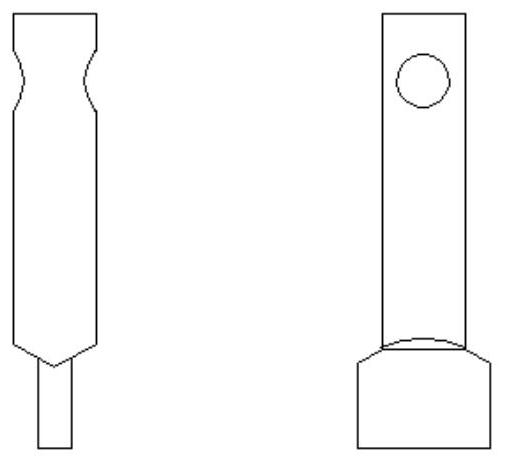
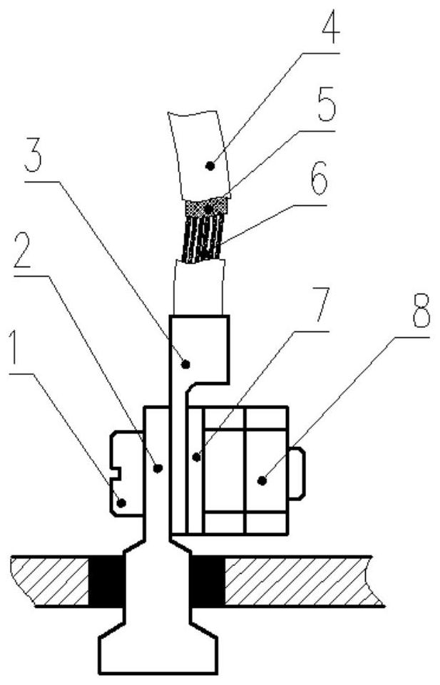
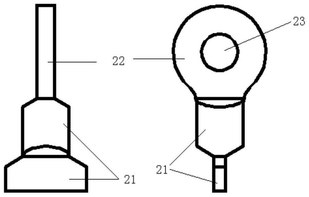
[0023] figure 2 Shown is a schematic diagram of the heat battery cable connection structure in a preferred implementation of the present invention; image 3 Shown is a schematic diagram of the electric energy output terminal of the thermal battery in a preferred implementation of the present invention.

[0024] see figure 2 , the thermal battery cable connection structure used in the 450°C environment of this embodiment includes screws 1, power output terminals 2, crimp terminals 3, high temperature resistant cables and nuts 8;

[0025] The screw 1 is inserted through the through hole on the electric energy output terminal 2;

[0026] The crimping terminal 3 is sleeved on the screw 1 and fastened by the nut 8, and is closely attached to the electric energy output termi...


PUM


Abstract

The invention thermal battery cable connection structure used in the environment of 450 DEG C comprises a screw, an electric energy output binding post, a crimping terminal, a high-temperature-resistant cable and a nut; the screw penetrates through the through hole in the electric energy output binding post; the crimping terminal is sleeved on the screw, is fastened through the nut, and is tightly attached to the electric energy output binding post; and the high temperature resistant cable is connected with the crimping terminal. The wired terminal is fixed on the electric energy output binding post through the nut and the screw, so that the potential safety hazard of short circuit between the positive electrode and the negative electrode of the thermal battery as well as between the positive electrode and the negative electrode and the shell caused by melting and flowing of the tin-lead solder at high temperature can be effectively avoided; and the risk that the electric energy output of the thermal battery is interrupted due to the fact that the lead falls off from the binding post after the tin-lead solder is molten can be effectively avoided.

Description

technical field [0001] The invention relates to the technical field of thermal batteries, in particular to a thermal battery cable connection structure used in a 450°C environment. Background technique [0002] The thermal battery is usually composed of a unit battery, an electrical interface and a mechanical interface. The unit battery is the core component of the thermal battery to generate electrical energy. The electrical interface is the channel for activating signal input and electrical energy output. The electrical interface mainly includes electrical connectors and cables. The unit battery Whether it is reliably connected to the cable determines whether the thermal battery can normally complete the intended task. [0003] The conventional working temperature range of the thermal battery is -50℃~+70℃. The connection between the unit battery and the cable adopts the conventional soldering method, that is, the cable is wound and welded on the terminal post on the top of...

Claims


Application Information

Patent Timeline
IPC IPC(8): H01R4/38H01B7/29H01M6/36H01M50/581H01M50/588
CPCH01R4/38H01B7/292H01M6/36
Inventor 高文秀袁光明周萍张鸿姜义田张燕青丁智伟
Owner SHANGHAI INST OF SPACE POWER SOURCES
Learn More