
Electronic timepiece, and method of power supply and time adjustment thereof

An electronic control and power supply technology is applied in the fields of electronically controlled timepieces, power supply control of electronically controlled timepieces, and time correction of electronically controlled timepieces, and can solve problems such as voltage rise, time error, and increase in spring size, etc. Achieve the effect of reducing power consumption, eliminating errors, and eliminating indication deviations

Inactive Publication Date: 2003-12-24
SEIKO EPSON CORP
View PDF0 Cites 0 Cited by
  • Summary
  • Abstract
  • Description
  • Claims
  • Application Information

AI Technical Summary

Problems solved by technology

[0016] However, increasing the capacitance of the capacitor slows down the rise of the power supply voltage, so it takes a long time to raise the voltage from a state where no charge has accumulated in the power supply capacitor, for example, as when the mainspring is released and then stopped.
That is, the hands will not be able to indicate the correct time for a long time from the start of winding the mainspring to the rise of the power supply voltage.
At this time, depending on the state, the user may mistakenly think that the watch is malfunctioning, so it is difficult to increase the capacitance of the capacitor.
[0017] In addition, it is also considered that increasing the power generation capacity of the generator can be charged in a short time, but the size of the generator will increase accordingly, and the torque of the spring that supplies mechanical energy to the generator will increase. , so it is necessary to increase the size of the mainspring, which cannot be used when the plane size and thickness are limited like a watch.
[0018] In addition, in various electronically controlled timepieces other than electronically controlled mechanical timepieces, such as self-winding power generation timepieces, solar rechargeable timepieces, and battery-type timepieces, time correction operations are sometimes performed in order to reduce power consumption and prolong driving time. At this time, the oscillation circuit or IC is also stopped. At this time, it may take several seconds to tens of seconds to achieve the stable operation of the oscillation circuit. At this time, a time error will occur.

Method used


Image

  • Electronic timepiece, and method of power supply and time adjustment thereof
  • Electronic timepiece, and method of power supply and time adjustment thereof
  • Electronic timepiece, and method of power supply and time adjustment thereof

Examples


Embodiment 4

[0271] In this embodiment, only the diode 38 having a reverse leakage current constitutes the charging control circuit 35 . At this time, when current is charged from the generator 20 to the respective capacitors 31 and 32, the charging current charged to the auxiliary capacitor 32 is only the reverse leakage current of the diode 38, which is very small, so most of the charging current flows into the main capacitor. 31. Therefore, as in the above-described embodiment, the voltage of the main capacitor 31 can be raised rapidly, so that the driving circuit 57 can be shifted to the control state in a short time.

[0272] In addition, when the charge is held in the auxiliary capacitor 32, the current can also be charged from the auxiliary capacitor 32 to the main capacitor 31 through the diode 38, so that the driving circuit 57 can be driven very quickly and the loss of current can be reduced.

[0273] In addition, in addition to obtaining the same effects as (3-1) to (3-9) of th...

Embodiment 5

[0274] Next, Embodiment 5 of the present invention will be described with reference to FIG. 23 and FIG. 24 . In this embodiment, the indication error correcting device 200 of the above-mentioned embodiment 2 is provided in the brake control circuit 56 of the above-mentioned embodiment 3.

[0275] Therefore, when the charge is held on the auxiliary capacitor 32, when the time correction operation ends and the switch 361 is turned on, current is charged from the auxiliary capacitor 32 to the main capacitor 31 through the diode 38, so that the driving circuit 57 can be driven very quickly. In addition, when the drive circuit 57 operates, the instruction error correcting device 200 controls the braking of the generator 20 in consideration of correction values ​​corresponding to the oscillation start time and temperature, as in the second embodiment, so that the instruction error can be eliminated.

[0276] In addition, even when no charge is held on the auxiliary capacitor 32, whe...


PUM


Abstract

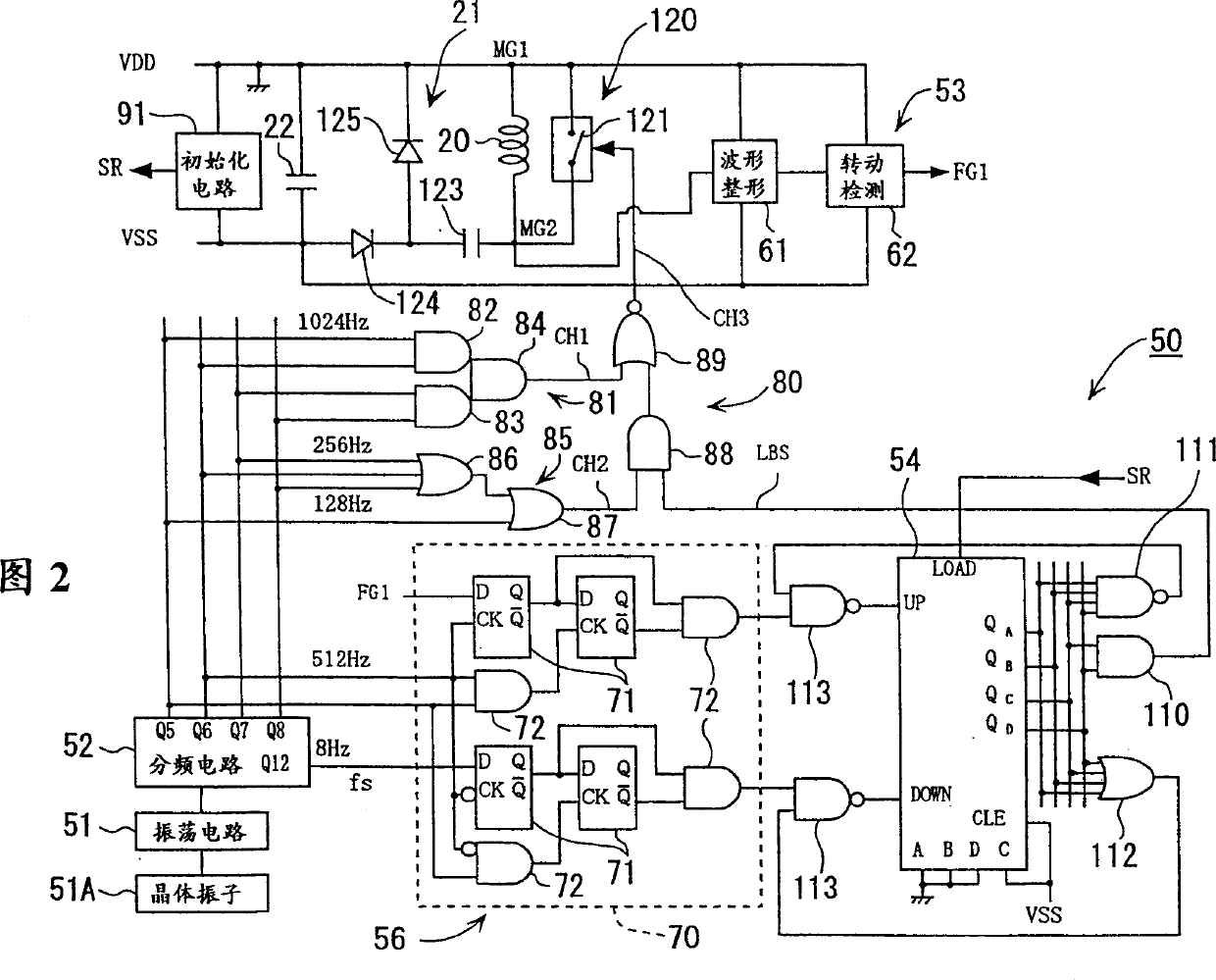
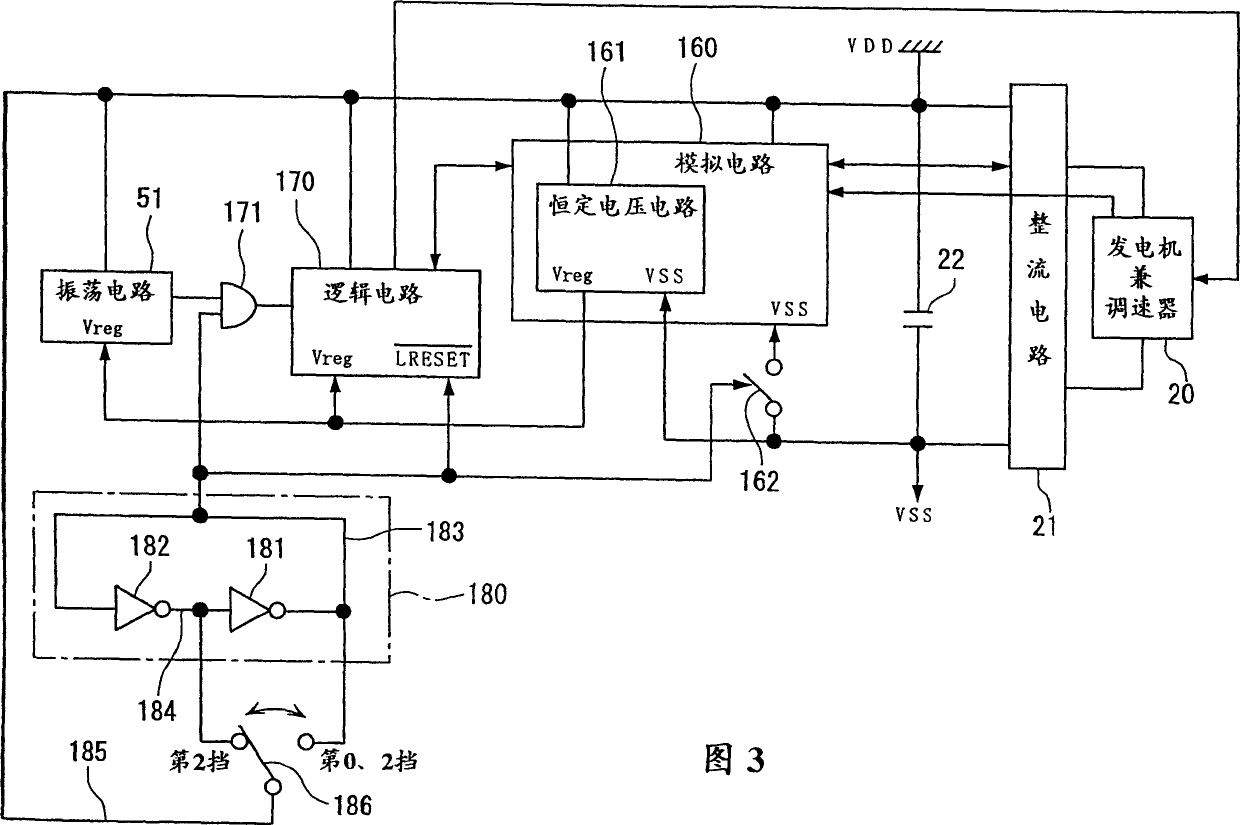
An electronic timepiece comprises an analog circuit (160) driven by a power supply (22), a logic circuit (170) driven by a voltage regulator (161) forming part of the analog circuit, an oscillator circuit (51) driven by the voltage regulator, a power supply switch (162) for cutting off power to all the analog circuits except the voltage regulator during a time adjustment, and a clock cut gate (171) capable of blocking the clock signal from the oscillator circuit to the logic circuit. Since the oscillator circuit and the voltage regulator are only operated during a time adjustment, the timepiece consumes less power but is accurate in time indication.

Description

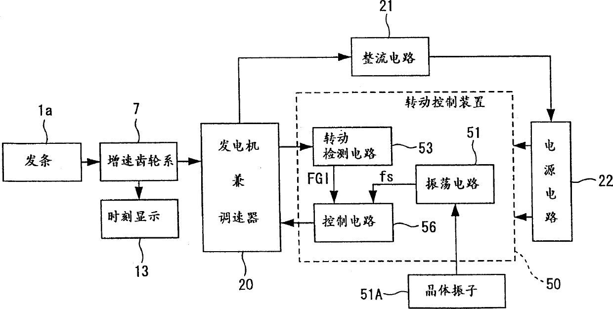
technical field [0001] The present invention relates to an electronically controlled timepiece that controls the movement of hands based on signals of an oscillation circuit using a time standard source such as a crystal oscillator, a power supply control method for the electronically controlled timepiece, and a time correction method for the electronically controlled timepiece. Background technique [0002] As one of electronically controlled timepieces controlled by an IC or a crystal oscillator, there is known one that converts the mechanical energy when the mainspring is released into electrical energy by a generator, and uses the electrical energy to operate a rotation control device to control the coil in the generator. An electronically controlled mechanical timepiece that accurately displays the time by driving the hands fixed on the gear train that transmits the mechanical energy of the mainspring to the generator according to the value of the current flowing in it. ...

Claims


Application Information

Patent Timeline
Patent Type & Authority Patents(China)
IPC IPC(8): G04C10/00G04G5/00G04G19/00G04G19/12
CPCG04G19/12G04G5/00G04G19/00G04C10/00
Inventor 中村英典小池邦夫清水荣作
Owner SEIKO EPSON CORP
Learn More