
Closed rotary type annular turbojet steam wheel

A steam wheel and rotary technology, applied in stators, engine components, machines/engines, etc., can solve problems affecting service life, parts corrosion, steam waste, etc., and achieve the effects of prolonging service life, avoiding corrosion, and improving efficiency

Active Publication Date: 2021-08-06
张龙
View PDF7 Cites 0 Cited by
  • Summary
  • Abstract
  • Description
  • Claims
  • Application Information

AI Technical Summary

Problems solved by technology

[0003] Traditional steam turbine steam is sprayed in an open manner. After spraying, the steam will be lost, which not only causes waste of steam, but also causes the steam to drift everywhere in the steam turbine, which easily causes corrosion of parts and affects its service life.

Method used


Image

  • Closed rotary type annular turbojet steam wheel
  • Closed rotary type annular turbojet steam wheel
  • Closed rotary type annular turbojet steam wheel

Examples


Embodiment 1

[0044] Embodiment 1, the embodiment in which the intermediate shaft is the power take-off shaft

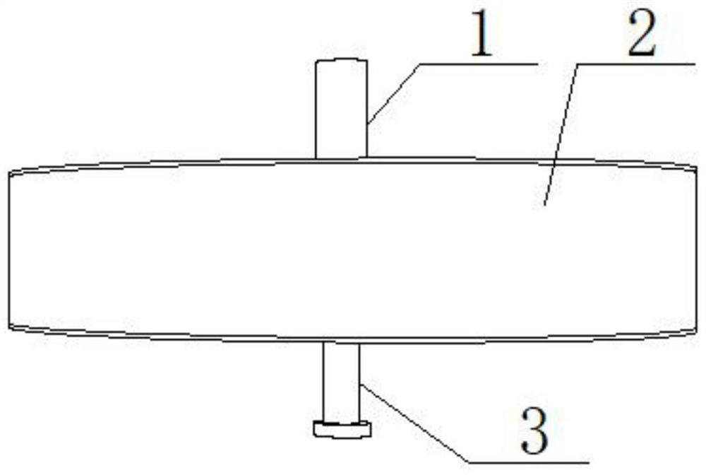
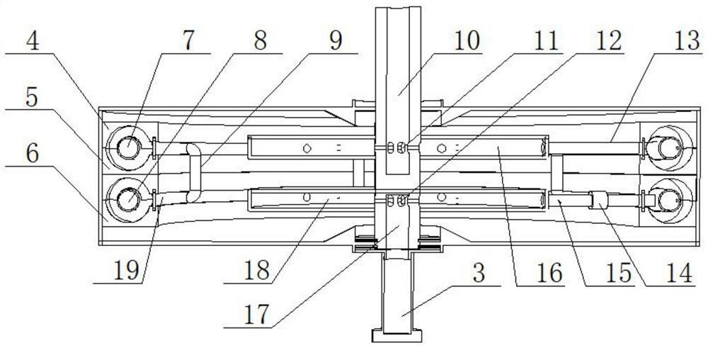
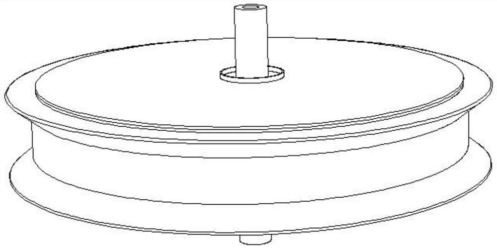
[0045] attached by Figure 1-2 as shown,

[0046] The sealed injection chamber is a one-stage and two-stage sealed injection chamber structure. For the convenience of assembly, the lower vortex of the upper single-stage sealed injection chamber and the upper vortex of the lower single-stage sealed injection chamber can be designed as an integrated structure. form the middle vortex,

[0047] Specifically, the structure of the two-stage sealed injection chamber includes an upper vortex 4, a middle vortex 5, and a lower vortex 6 fixedly mounted on the inner wall of the casing, and the middle vortex and the lower vortex are fastened together to form a primary injection space. , the upper vortex and the middle vortex are fastened to form a secondary injection space, and a primary injection ring 8 and a secondary injection ring 7 are respectively installed in the primary injection spa...

Embodiment 2

[0054] Embodiment 2, the embodiment in which the casing is a power output

[0055] The difference between this embodiment 2 and embodiment 1 is that the intermediate shaft of this embodiment 2 is a fixed embodiment, and compared with embodiment 1, the structure is simpler and the torque is also larger.

[0056] The intermediate shaft in this embodiment is a structure in which the upper and lower ends pass through the upper and lower ends of the housing respectively, and the housing rotates around the intermediate shaft through bearings.

[0057] When in use, the power source (steam) is directly connected to the intake air passage at the bottom of the intermediate shaft, the steam enters the exhaust collector, and the steam in the exhaust collector enters the first-stage injection ring from the intake branch pipe, and the first-stage injection The ring injects steam to the resistance sheet of the sealed injection chamber, and uses the injection force to push the sealed injectio...


PUM


Abstract

The invention relates to a closed rotary type annular turbojet steam wheel. The annular turbojet steam wheel comprises a shell, a middle shaft, a sealed jet cavity, a jet ring, a sealing ring piece, an exhaust collector and an air inlet collector; the sealed jet cavity is fixedly mounted on the inner wall of the shell, the jet ring is arranged in the sealed jet cavity, and the sealing ring piece is rotationally mounted on the inner ring sealing jet cavity of the jet ring; the middle shaft is coaxially mounted in the middle of the shell, the exhaust collector and the air inlet collector sequentially and coaxially penetrate through the middle shaft in the shell from bottom to top, air inlet branch pipes are evenly distributed on the outer wall of the exhaust collector at intervals, exhaust branch pipes penetrate through the sealing ring piece to be connected with the jet ring, and the exhaust branch pipes evenly distributed at intervals penetrate through the sealing ring piece to connect the jet ring with the air inlet collector. According to the closed rotary type annular turbojet steam wheel, the steam loss in the jet process is effectively reduced, and the efficiency of steam acting is improved; meanwhile, corrosion of steam to parts is avoided, and the service life of the steam wheel is prolonged.

Description

technical field [0001] The invention belongs to the field of engines, and relates to a steam turbine, in particular to a closed rotary annular turbojet steam turbine. Background technique [0002] A steam turbine is a rotary prime mover that uses steam or other airflow as a power source. It has the advantages of high power, simple structure, few wearing parts, low vibration, and low noise. The steam wheel is the rotating work part of the steam turbine. It is mainly composed of steam (air flow) nozzles (also called stationary blades) and moving blades (also called blades). The nozzles are fixed on the casing or the diaphragm, and the moving blades fixed on the roulette. The working principle of the traditional steam turbine is: the steam (airflow) is connected to the nozzle of the steam wheel, and the steam is sprayed out through the nozzle (stationary vane) to act on the impeller (blade) fixed on the wheel disk, and the impeller drives the wheel disk to rotate, rotate The ...

Claims


Application Information

Patent Timeline
Patent Type & Authority Applications(China)
IPC IPC(8): F01D9/04F01D25/30
CPCF01D9/041F01D9/047F01D25/30
Inventor 张龙
Owner 张龙
Learn More