Blade, modeling method and manufacturing method thereof and air compressor

A compressor and blade profile technology, applied to mechanical equipment, machines/engines, liquid fuel engines, etc., can solve the problems of not considering the fine organization and regulation of blade passages, unsatisfactory improvement effects, and lack of fine regulation , to achieve the effect of avoiding poor practicability, improving the quality of flowing airflow, and breaking through performance bottlenecks

Active Publication Date: 2021-08-06
CENT SOUTH UNIV
View PDF9 Cites 5 Cited by
  • Summary
  • Abstract
  • Description
  • Claims
  • Application Information

AI Technical Summary

Problems solved by technology

However, due to the coupling effect between the vane and the channel in the limited space of the compressor channel, the improvement effect is often unsatisfactory or not universal
The reason is that due to the influence of the airfoil design idea of ​​the outflow airfoil, the existing primitive cascade design is more inclined to the airfoil design, while the internal flow of the compressor is a restricted space and has a flow direction / radial direction under the influence of the polygonal curvature. Strong pressure gradients, inherently unsteady flow
The design idea based on the blade shape basically does not consider the fine organization and regulation of the flow in the blade channel, and lacks the idea of ​​actively considering the fine regulation of the flow in the cascade channel at the beginning of the design

Method used


Image

  • Blade, modeling method and manufacturing method thereof and air compressor
  • Blade, modeling method and manufacturing method thereof and air compressor
  • Blade, modeling method and manufacturing method thereof and air compressor

Examples


Embodiment Construction

[0033] In order to facilitate the understanding of the present invention, the present invention will be described in more detail below in conjunction with the accompanying drawings and preferred embodiments, but the protection scope of the present invention is not limited to the following specific embodiments.

[0034] Unless otherwise defined, all technical terms used hereinafter have the same meanings as commonly understood by those skilled in the art. The terminology used herein is only for the purpose of describing specific embodiments, and is not intended to limit the protection scope of the present invention.

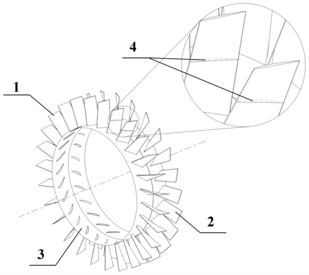
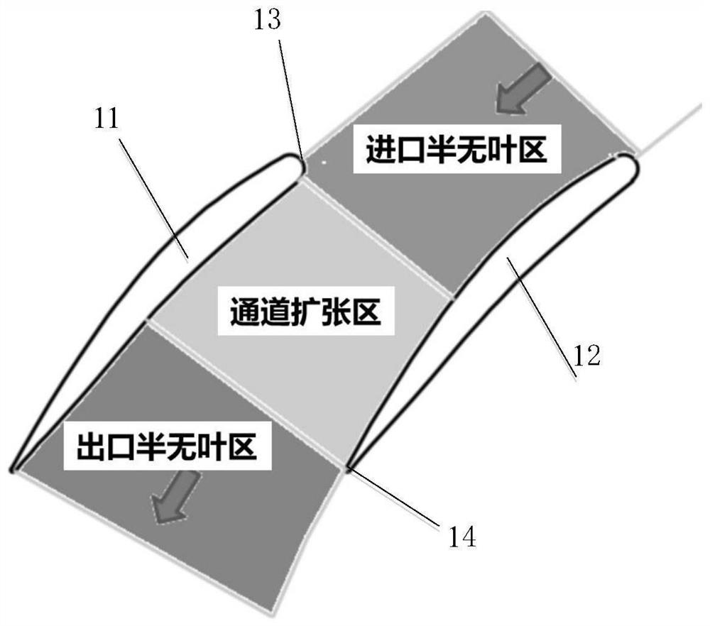
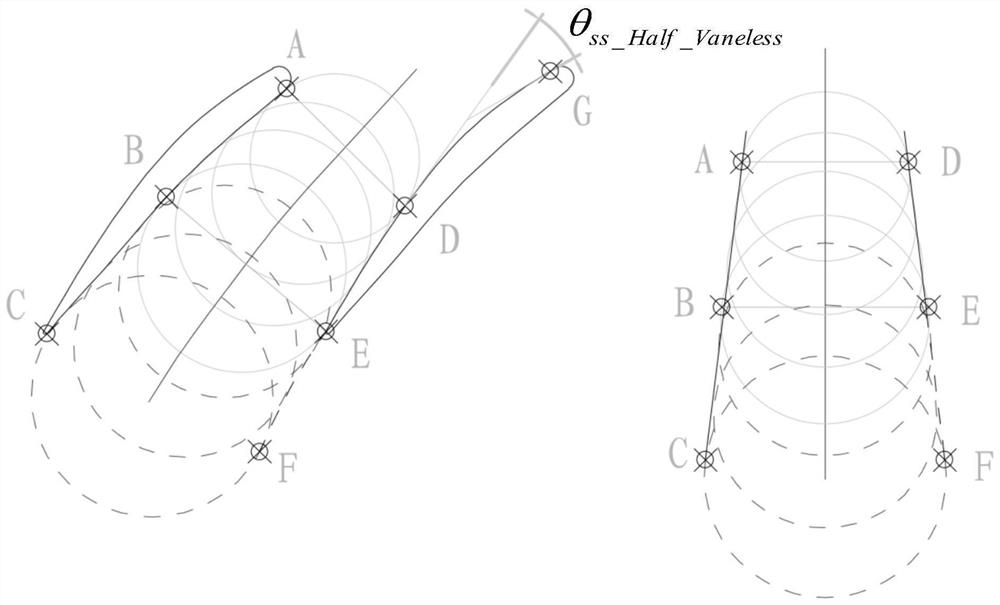
[0035] In the molding method of the compressor blade of the present invention, according to the areas divided by the flow channel, first determine the leading edge side endpoints of the suction surface profile line and the pressure surface profile line of the flow channel, and then determine the blade profile lines forming the boundaries of each partition in turn, ...


PUM


Abstract

The invention discloses a blade, a modeling method and manufacturing method thereof and an air compressor. The modeling method comprises the steps that a flowing channel is sequentially divided into an inlet semi-vaneless area, a channel expansion area and an outlet semi-vaneless area in the gas flowing direction; front edge side end points of a suction surface molded line and a pressure surface molded line of the flowing channel are determined; blade molded lines forming the boundaries of the inlet semi-vaneless area, the channel expansion area and the outlet semi-vaneless area are sequentially determined, and the channel expansion angle of the whole flowing channel is regulated and controlled; on the basis of the determined molded lines, modeling of the primitive-level blade profiles is completed, and then the primitive-level blade profiles are stacked to form the three-dimensional blade. The modeling method has the advantage that the diffusion degree of an expansion channel is controllable, the quality of flowing airflow in the expansion channel of the axial flow air compressor blade is improved helpfully, pneumatic matching between blade rows is improved, and the efficiency of the axial flow air compressor is improved; and the modeling method has good applicability to radial/axial diffuser blades of a centrifugal air compressor and high-low pressure stage rotor/stator blades of a turbine.

Description

technical field [0001] The invention belongs to the field of compressor / turbine design, and in particular relates to a compressor / turbine blade, a molding method and a manufacturing method thereof, and a compressor. Background technique [0002] An axial flow compressor is a compressor in which the airflow flows substantially parallel to the axis of the rotating impeller. Due to the advantages of large flow rate and high efficiency, axial flow compressors have been widely used in medium and large aero-engines, ground gas turbines and civil ventilation equipment. In order to further reduce the fuel consumption rate of aero-engines and ground gas turbines and the power consumption of civil ventilation equipment, one of the important measures is to improve the efficiency of axial flow compressors, which promotes the development of the basic element-level configuration of compressors in the direction of refinement. [0003] At present, in the aerodynamic design system of the co...

Claims


Application Information

Patent Timeline
Patent Type & Authority Applications(China)
IPC IPC(8): F04D29/38
CPCF04D29/324Y02E10/72
Inventor 王毅
Owner CENT SOUTH UNIV
Why Eureka
Try Eureka