
Photomagnetic memory structure

A memory and opto-magnetic technology, which is applied in information storage, record information storage, and the structure of arm parts, etc. It can solve the problems of not meeting the requirements of energy saving and high energy efficiency ratio, not directly improving the data processing speed, and the proportion of effective power of the system is low. problem, to achieve the effect of overcoming easy scratches and bursting, avoiding heat dissipation problems, and occupying a small area

Active Publication Date: 2021-08-06
王旭
View PDF11 Cites 0 Cited by
  • Summary
  • Abstract
  • Description
  • Claims
  • Application Information

AI Technical Summary

Problems solved by technology

[0006] (2) Slow reading and writing speed: In order to meet the requirements of timely response to random high-speed reading and writing of data in the existing technology, the disk must always maintain a high-speed rotation state regardless of whether the memory is in an idle state without data reading or writing; and the disk rotates at a high speed for a long time The heat loss caused by friction is relatively large, and the effective power ratio of the system is relatively low, which cannot meet the requirements of energy saving and high energy efficiency ratio
However, neither of these two methods directly improve the internal structure of a single memory system. For the mechanical structure of a single magnetic / optical disk memory, there is no effective means to directly improve the data processing speed.

Method used


Image

  • Photomagnetic memory structure
  • Photomagnetic memory structure
  • Photomagnetic memory structure

Examples


Embodiment 1

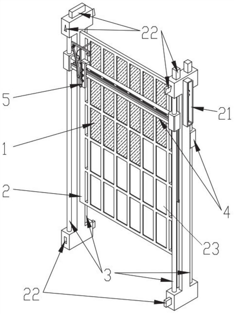
[0038] This embodiment provides a magneto-optical memory structure, which can be installed vertically, occupying a high space and less occupied area; as figure 1 As shown, it includes a main frame 2 on which an array of storage disks 1 is installed.

[0039] In this embodiment, the main frame 2 has an H-shaped structure, which includes a support portion and a disk mounting portion, and the disk mounting portion is arranged in a rectangular structure; taking the vertical state of the main frame 2 as a reference, its height direction is longitudinal, and its length is The direction is transverse; the support part is symmetrically installed on both sides of the disc installation part in the transverse direction. In order to facilitate the installation of slide rails, the supporting part of this embodiment is arranged as an I-shaped structure. It can be understood that in other embodiments, the supporting portion and the disk mounting portion may also be configured in other struc...

Embodiment 2

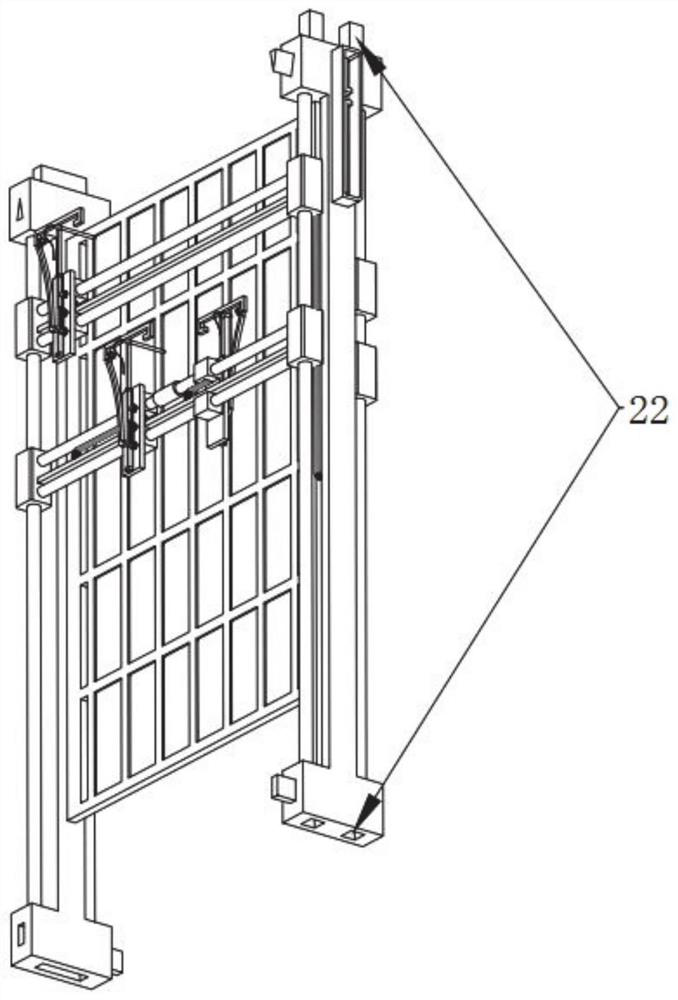
[0071] This embodiment provides a magneto-optical memory structure, such as Image 6 As shown, the difference from Embodiment 1 is that at least two second slide rails 4 can be distributed on the same side of the main frame 2, and at least two read-write assemblies 5 can be distributed on each second slide rail 4. The same second slide rail Two adjacent read-write components 5 on the 4 are separated by an anti-collision limit ring 41 arranged between the two, so as to avoid collision between the two. If necessary, the anti-collision limiting ring 41 can also be installed on the first slide rail 3 .

[0072] Wherein, the installation directions of two adjacent read-write components 5 located on the same side of the main frame are different, so as to avoid the edges of the two permeable cores 542 from colliding.

[0073] The lengths of the read-write heads 55 equipped with the read-write assemblies 5 with different installation directions as described above are different.


PUM


Abstract

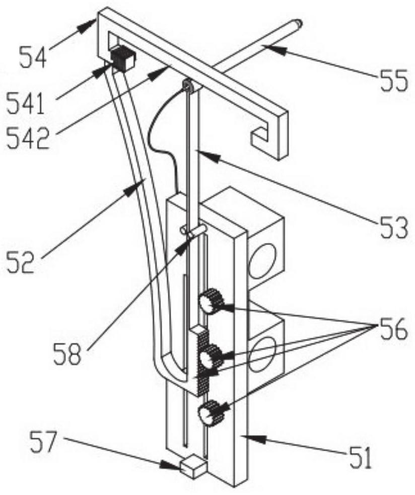
The invention provides a photomagnetic memory structure. According to the technical scheme, the photomagnetic memory structure comprises a main frame provided with a memory disk array, first sliding rails are symmetrically installed on the two transverse sides of the main frame, one or more second sliding rails are connected between the first sliding rails located on the same side of the main frame, and the second sliding rails are slidably connected with a read-write assembly; the read-write assembly comprises a read-write head connected to one end of the vibration arm and an electromagnet arranged on the side face of the vibration arm, and the electromagnet and the other end of the vibration arm are connected into a whole through a connecting rod. The electromagnet generates a magnetic field in a set period to attract the vibrating arm to drive the read-write head to perform simple harmonic vibration, so that the read-write head forms a set data read-write track on the surface of the memory disk. No high-speed rotating assembly is arranged, the number of storage disks and read-write assemblies is easy to expand, and storage capacity expansion and read-write speed improvement of a single magnetic / optical disk storage product are facilitated.

Description

technical field [0001] The invention relates to the field of magnetic / optical disk storage, in particular to an optical magnetic storage structure. Background technique [0002] Traditional magnetic / optical disk storage and even early floppy disks are developed from the early disc structure. The structure and its working principle are: driven by a motor located at the axis of the circular disc, one or more discs are arranged at intervals on the same axis. The disc rotates continuously at high speed, and the magnetic head / optical head on each side of the disc can move radially from the outer ring to the inner ring under the drive of the read-write arm. After each rotation of the disc, the read-write arm moves Move the read-write head a little inward to switch the data storage tracks of the inner and outer rings, so the data storage tracks are many concentric rings or spirals. The data storage principles of magnetic disks and optical disks are respectively based on magnetic s...

Claims


Application Information

Patent Timeline
IPC IPC(8): G11B5/012G11B5/02G11B5/48G11B5/50G11B7/0037G11B7/0045G11B7/005G11B7/12
CPCG11B5/012G11B5/02G11B5/4826G11B5/4833G11B5/50G11B5/596G11B7/0037G11B7/0045G11B7/005G11B7/12
Inventor 王旭
Owner 王旭
Learn More