
Iron removal and mineral separation machine

A concentrator and iron rod technology, applied in the direction of solid separation, chemical instruments and methods, magnetic separation, etc., can solve the problems of unclean removal of iron, high cost, unfavorable industrial production, etc., to save time for collecting iron particles, The effect of reducing labor force and improving efficiency

Active Publication Date: 2021-08-10
唐山金信硅业有限公司
View PDF8 Cites 0 Cited by
  • Summary
  • Abstract
  • Description
  • Claims
  • Application Information

AI Technical Summary

Problems solved by technology

[0006] Aiming at the deficiencies of the prior art, the present invention provides an iron-removing concentrator, which solves the problem that in the beneficiation process, in the case of high iron content requirements, it is necessary to use iron-removing equipment to concentrate and remove the raw materials after rough selection. iron, and even remove iron several times to meet the requirements, the efficiency of iron removal is low, and the removal of iron is not clean, time-consuming, laborious, expensive, and not conducive to industrial production

Method used


Image

  • Iron removal and mineral separation machine
  • Iron removal and mineral separation machine
  • Iron removal and mineral separation machine

Examples


Embodiment 1

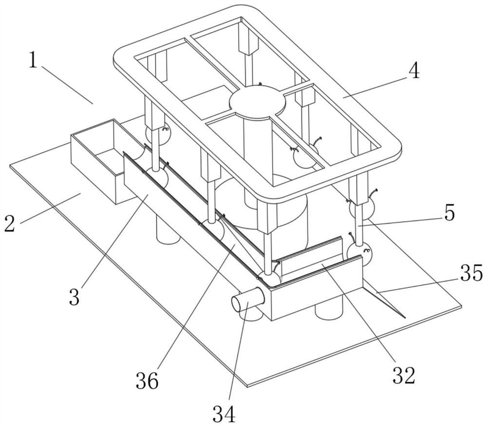
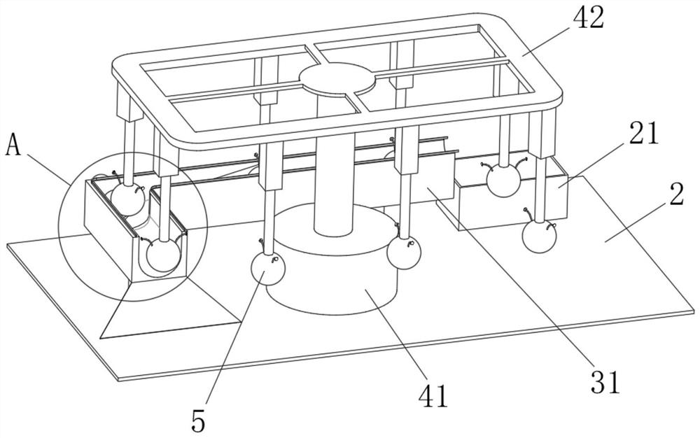
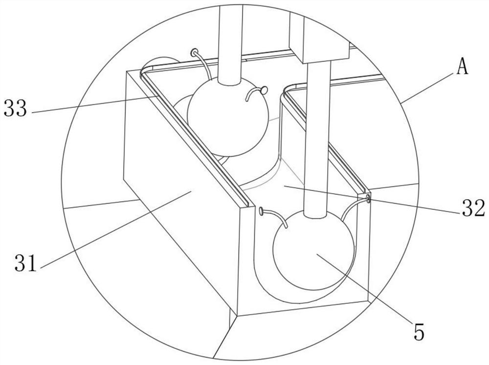
[0037] see Figure 1-4 , the present invention provides a technical solution: a mineral processing machine for removing iron, including a base 2, a mineral processing mechanism 3, a circulation mechanism 4 and a mineral processing machine body 1 for removing iron, and the mineral processing mechanism 3 includes a guide block 31, which guides The inside of the block 31 is provided with a guide groove 32, the top of the guide block 31 is fixedly connected with a conductive rail 33, the bottom receiving column of the guide block 31 is fixedly connected with the top of the base 2, and the left side of the guide block 31 is fixedly connected with a feed pipe 34 , the right end of the feed pipe 34 runs through the guide block 31 and extends to the inside of the guide groove 32, the right side of the guide block 31 is fixedly connected with the material receiving plate 35, the circulation mechanism 4 includes an engaging column 41, the bottom of the engaging column 41 is connected to ...

Embodiment 2

[0042] see Figure 1-5 On the basis of Embodiment 1, the present invention provides a technical solution: the iron removal mechanism 5 includes a sphere 51, the top of the sphere 51 is slidingly connected to the inside of the electric slide rail 42 through an elastic telescopic rod, and the inside of the sphere 51 is fixedly connected with Conductive sheet 52.

[0043] The inside of the ball 51 is fixedly connected with a conductive strip 53 , the bottom of the conductive strip 53 is electrically connected to the inside of the conductive sheet 52 , and the top of the conductive strip 53 is electrically connected to the inside of the conductive rail 33 through the rotating block.

[0044] The inside of the conductive sheet 52 is fixedly connected with an electromagnetic telescopic rod 54, and the bottom of the electromagnetic telescopic rod 54 is fixedly connected with a squeeze disc 55, and an insulating cavity 56 is opened inside the ball 51, and the outer side of the squeeze...

Embodiment 3

[0048] see Figure 1-6 , on the basis of Embodiment 1 and Embodiment 2, the present invention provides a technical solution: the iron-absorbing mechanism 58 includes an electromagnetic strip 581, and the bottom of the electromagnetic strip 581 is fixedly connected with a piston plate 582, and the bottom of the piston plate 582 passes through a spring assembly It is fixedly connected with the outer side of the ball center 57, and the outer side of the electromagnetic strip 581 is rotatably connected with an iron-absorbing rod 583 through a reset piece.

[0049] One end of the iron-absorbing rod 583 away from the electromagnetic strip 581 is connected with a rolling ball 584 through a rotating shaft, the outer side of the rolling ball 584 is slidingly connected with the inside of the sphere 51, and the outer side of the iron-absorbing rod 583 is fixedly connected with a wear-resistant bag 585, which The inside of the 585 is provided with a magnetic strip 586 , and the side of th...


PUM


Abstract

The invention discloses an iron removal and mineral separation machine, which comprises an iron removal andmineral separationmachine body composed of a base, a mineral separationmechanism, a circulating mechanism and an iron removal mechanism, wherein the mineral separation mechanism comprises a guide block, a guide groove is formed in the guide block, a conducting rail is fixedly connected to the top of the guide block, the bottom bearing column of the guide block is fixedly connected with the top of the base, a feeding pipe is fixedly connected to the left side of the guide block, the right end of the feeding pipe penetrates through the guide block and extends into the guide groove, and a receiving plate is fixedly connected to the right side of the guide block. The invention relates to the technical field ofmineral separation. According to the iron removal andmineral separation machine, the problems that in the mineral separationprocess, in the occasion with the high requirement for the iron content, iron removal equipment needs to be used for conducting concentration iron removal and even multiple times of iron removal on raw materials obtained after roughing, so that the requirement is met, the iron removal efficiency is low, iron removal is not thorough, time and labor are wasted, the cost is high, and industrial production is not facilitated are solved.

Description

technical field [0001] The invention relates to the technical field of mineral processing, in particular to a mineral processing machine for removing iron. Background technique [0002] Mineral dressing is based on the physical and chemical properties of different minerals in the ore. After the ore is crushed and ground, gravity separation, flotation, magnetic separation, electric separation and other methods are used to separate useful minerals from gangue minerals. Various symbiotic (associated) useful minerals are separated from each other as much as possible, and harmful impurities are removed or reduced to obtain raw materials for smelting or other industries. [0003] According to Chinese patent CN104084300A, the present invention relates to an iron removal concentrator, including a first bracket, a second bracket, an iron removal pulley I, an iron removal pulley II, a magnet, an iron removal belt, a feed pulley I, a feed Pulley II, feeding belt and iron ore blanking ...

Claims


Application Information

Patent Timeline
Patent Type & Authority Applications(China)
IPC IPC(8): B03C1/02
CPCB03C1/02
Inventor 卫富昌
Owner 唐山金信硅业有限公司
Learn More